4000 SRM 736 Description and Operation
General
This section contains the description, operation, and repair procedures for the masts. Information on sideshift
carriage is also included in the section.
Description and Operation
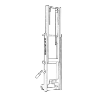
Vertical frames of a mast are called weldments. See
Figure 1. Channels, load rollers, and crossmembers
are parts of the weldments. Channels on each side
of the weldment are support members of the mast
and tracks for load rollers. While lifting and lowering
a load, large forces are put on the mast assembly.
Load rollers reduce the friction between the channels
when the weldments move vertically.
1. FORKS
2. CARRIAGE
3. LOAD BACKREST
EXTENSION
4. OUTER
WELDMENT
5. INNER WELDMENT
6. LIFT CYLINDER
Figure 1. Mast Components
The mast can tilt forward and backward. Tilt cylin-
ders are installed between the frame of the lift truck
and outer weldment of the mast. For H3.50-5.50XM
(H70-120XM) lift trucks, the pivot mounts at the bot-
tom of the outer weldment connect the mast to the
lift truck. During tilt operation, the mast rotates on
pivot pins in the frame.
For S3.50-5.50XM and E3.50-5.50XL
3
(E70-120XL
3
)
model lift trucks, mast mounting hangers are at-
tached to the drive axle and connect the mast to the
lift truck. During tilt operation, the mast rotates on
the drive axle.
CARRIAGES
The carriage is a separate section that moves on load
rollers within vertical channels of the inner weld-
ment. Forks or other types of load handling equip-
ment are attached to the carriage. A load backrest
extension is installed on the carriage.
A sideshift carriage permits the operator to hydrauli-
cally change the lateral position of the load handling
device on the carriage.
TWO-STAGE MAST WITH LIMITED
FREE-LIFT
The two-stage mast with limited free-lift (LFL) has
two weldments, an outer weldment and an inner
weldment. See Figure 2. Outer weldment is con-
nected to the lift truck by pivot mounts and tilt
cylinders. The top of the outer weldment and the
base of the inner weldment have one load roller on
each side. These load rollers travel along channels
of the weldments. The angle of the load rollers per-
mits them to control the forces from the front, back,
and sides of the mast. Shims on the load rollers
control lateral clearance between weldments and
load rollers. Strip bearings are installed at the top of
each side of the outer weldment. Strip bearings keep
correct clearance (forward and backward) between
outer weldment and inner weldments.
1