Description and Operation 4000 SRM 736
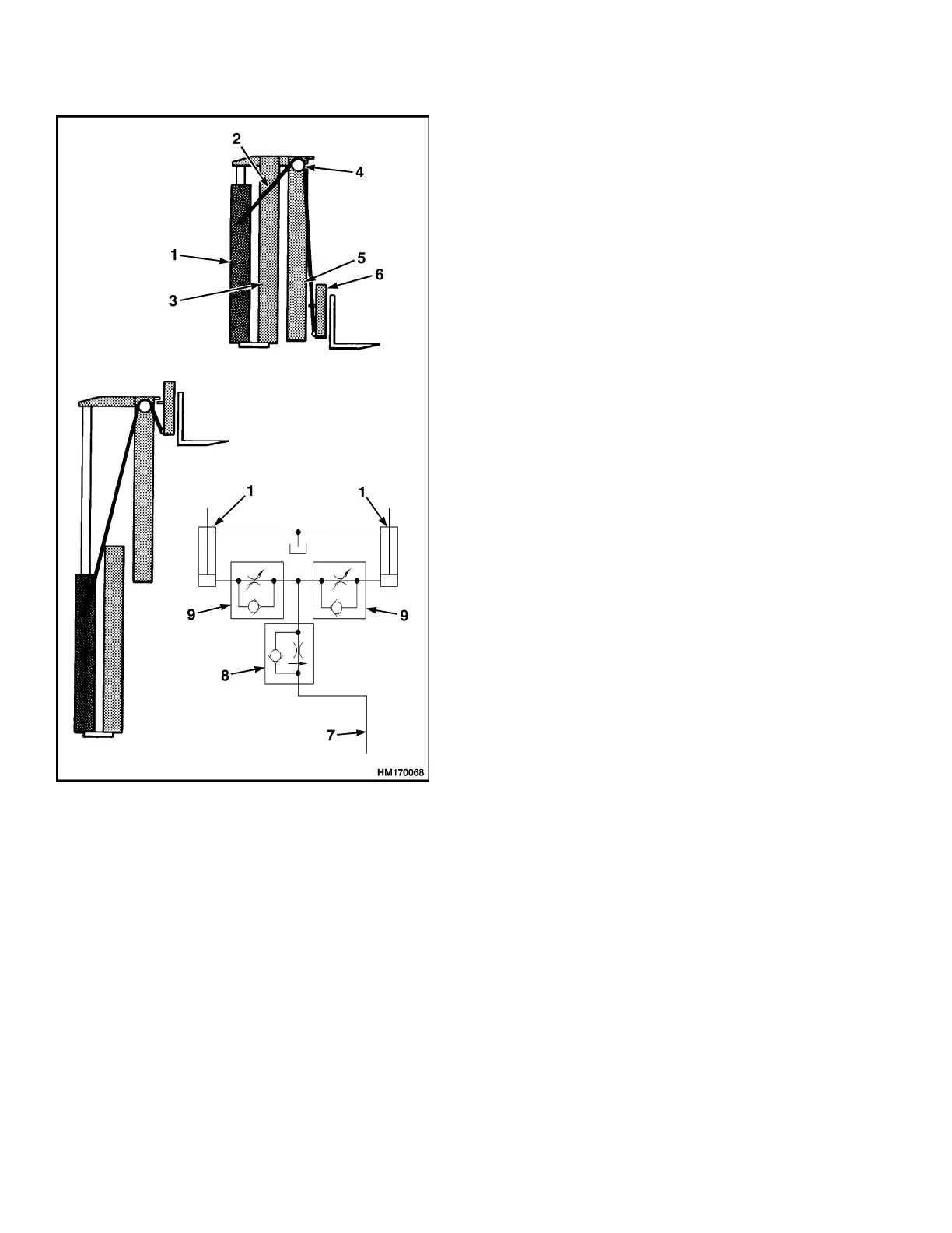
1. LIFT C
YLINDER (2)
2. LIFT CHAIN
3. OUTER
WELDM
ENT
4. CHAIN SHEAVE
5. INNER WELDMENT
6. CARRIA
GE
7. FROM M
AIN
CONTROL VALVE
8. EXTERNAL
LOWER
ING
CONTROL VALVE
9. INTERNAL
LOWER
ING
CONTROL VALVE
Figure 2. Two-Stage Mast With Limited
Free-Lift
The two-stage mast with limited free-lift has two sin-
gle-stage lift cylinders. Lift cylinders are installed at
the back of the outer weldment. The base of each lift
cylinder is held on a mount at the bottom of the outer
weldment by brackets. The top of each lift cylinder
(cylinder rod) fits into a guide at the top of the inner
weldment. A clamp holds the top of the lift cylinder
in position on the outer weldment. Operation of lift
cylinders extends and retracts the inner weldment.
Two lift chains control the movement of the carriage.
Chains are fastened to mounts near the top of the
outer weldment. The chains go up and over chain
sheaves on inner weldment and then connect to
the carriage. When lift cylinders extend, lift chains
transfer the force from lift cylinders to the carriage.
When lift cylinders retract, weight of the load, car-
riage, and inner weldment push oil from the lift cylin-
ders. Oil flows from lift cylinders, through lowering
control valves, main control valve, and then to the
hydraulic tank.
TWO-STAGE MAST WITH FULL FREE-LIFT
The two-stage mast with full free-lift (FFL) has an
inner weldment, an outer weldment, and three sin-
gle-stage lift cylinders. See Figure 3. It is called a
free-lift mast because the carriage can travel to the
top of the inner weldment without increasing mast
height. The free-lift mast has load roller and strip
bearing arrangements similar to the two-stage mast
with limited free-lift.
Two main lift cylinders are installed at the back of
the outer weldment. The base of each lift cylinder
sits in a mount at the bottom of the outer weldment.
The hydraulic fitting for each lift cylinder goes
through a hole in the mount. The top of each lift
cylinder (cylinder rod) fits into guides at the top of
the inner weldment.
Free-lift cylinder is installed in the inner weldment.
Main lift cylinder on the right side of the mast and
the free-lift cylinder each have an internal lower-
ing control valve. A single external lowering con-
trol valve is connected by tubing to all lift cylinders.
Two chain sheaves are installed on the cylinder rod
of the free-lift cylinder. Lift chains are connected to a
mount behind the free-lift cylinder. The chains then
go over the sheaves and are connected to the carriage.
Three lift cylinders are connected by hoses and tub-
ing. To extend the mast, oil from main control valve
flows to all lift cylinders at the same time. Free-lift
cylinder raises first because it lifts the least amount
of weight. Free-lift cylinder raises the carriage to the
top of the inner weldment. After the free-lift cylinder
reaches the end of its stroke, main lift cylinders be-
gin to extend and raise the inner weldment.
2