4000 SRM 340 Description and Operation
General
This section has the description, operation, and repair procedures for the Vista
®
masts for the 3,500 to 6,000 kg
(7,000 to 12,000 lb) capacity lift trucks. Information on the different types of sideshift carriages is also in-
cluded. The lift cylinders and the lowering control valves are described in the section Lift Cylinders 4000
SRM 1354000 YRM 135. The tilt cylinders are described in the section Tilt Cylinders 2100 SRM 103 .
Description and Operation
The vertical frames of a mast are called weldments.
See Figure 1. Channels, load rollers and crossmem-
bers are parts of the weldments. The channels on
each side of the weldment are the support members
of the mast and the tracks for the load rollers. Dur-
ing lifting and lowering a load, large forces are put
on the mast assembly. The load rollers reduce the
friction between the channels when the weldments
move vertically.
Each mast can tilt forward and backward. Tilt
cylinders are installed between the frame of the lift
truck and the outer weldment of the mast. The pivot
mounts at the bottom of the outer weldment connect
the mast to the lift truck. During the tilt operation,
the mast rotates on the pivot pins in the frame.
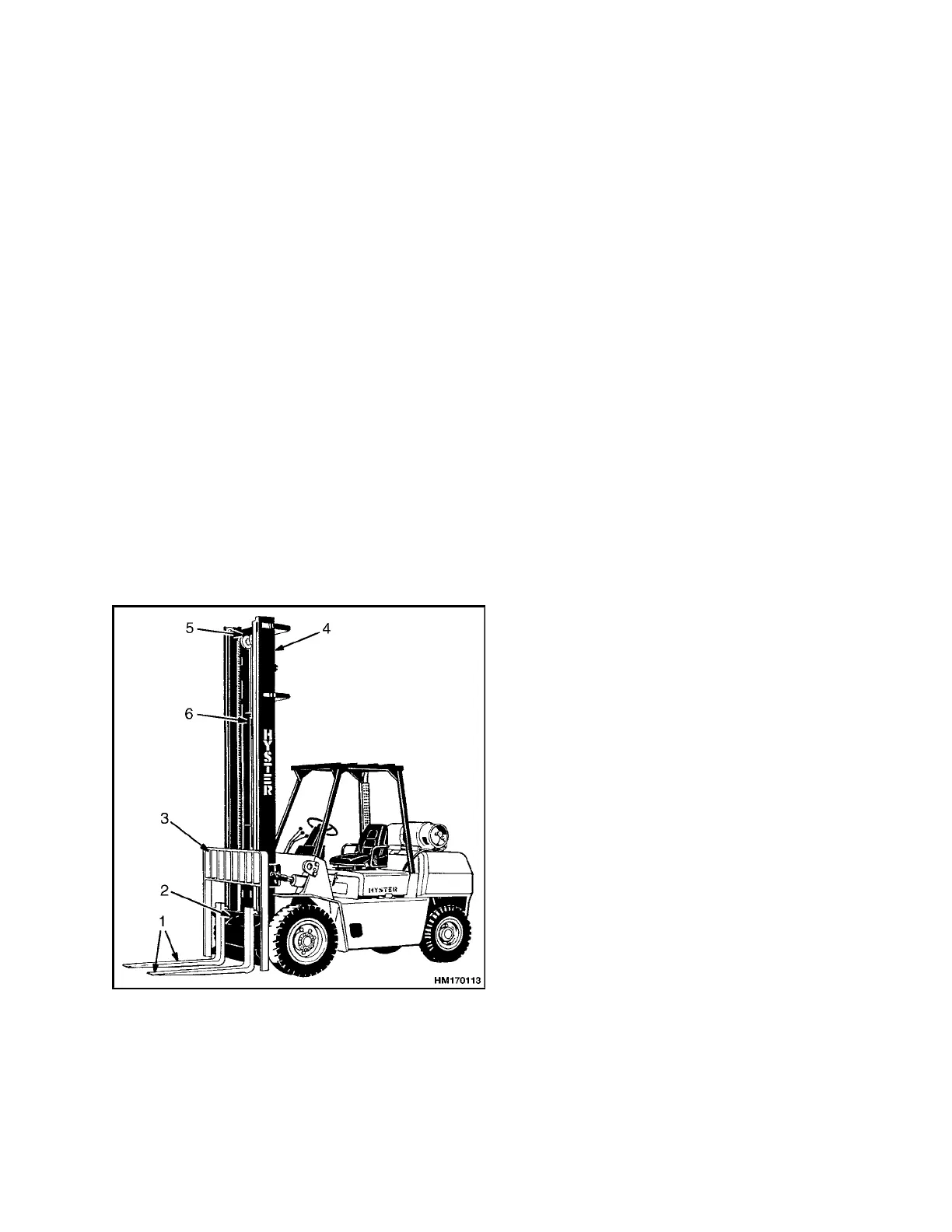
1. FORKS
2. CARRIAGE
3. LOAD BACKREST
EXTENSION
4. OUTER
WELDMENT
5. INNER WELDMENT
6. LIFT CYLINDER
Figure 1. Mast Components
CARRIAGES
The carriage is a separate section that moves on load
rollers within the vertical channels of the inner weld-
ment. Forks or other types of load handling equip-
ment are attached to the carriage. A load backrest
extension is installed on the carriage.
A sideshift carriage permits the operator to hydrauli-
cally change the lateral position of the load handling
device on the carriage.
TWO-STAGE MAST WITH LIMITED
FREE-LIFT
The Vista Two-Stage mast has two weldments, an
outer weldment and an inner weldment. See Fig-
ure 2. The outer weldment is connected to the lift
truck by the pivot mounts and the tilt cylinders. The
top of the outer weldment has one load roller on each
side. The base of the inner weldment has one load
roller on each side. These load rollers travel along
the channels of the weldments. The angle of the load
rollers permits them to control the forces from the
front, back and sides of the mast. The shims on the
load rollers control the lateral clearance between the
weldments and the load rollers. Strip bearings are
installed at the top of each side of the outer weld-
ment. The strip bearings keep the correct clearance
(forward and backward) between the outer weldment
and the inner weldment.
The two-stage mast has two single stage lift cylin-
ders. The lift cylinders are installed at the back of the
outer weldment. The base of each lift cylinder sits in
a mount at the bottom of the outer weldment. The
hydraulic fitting for each lift cylinder goes through a
hole in the mount. The top of each lift cylinder (cylin-
der rod) fits into a guide at the top of the inner weld-
ment. A bracket on the cylinder shell holds the lift
cylinder in position on the outer weldment. Opera-
tion of the lift cylinders extends and retracts the in-
ner weldment.
1