4000 SRM 340 Description and Operation
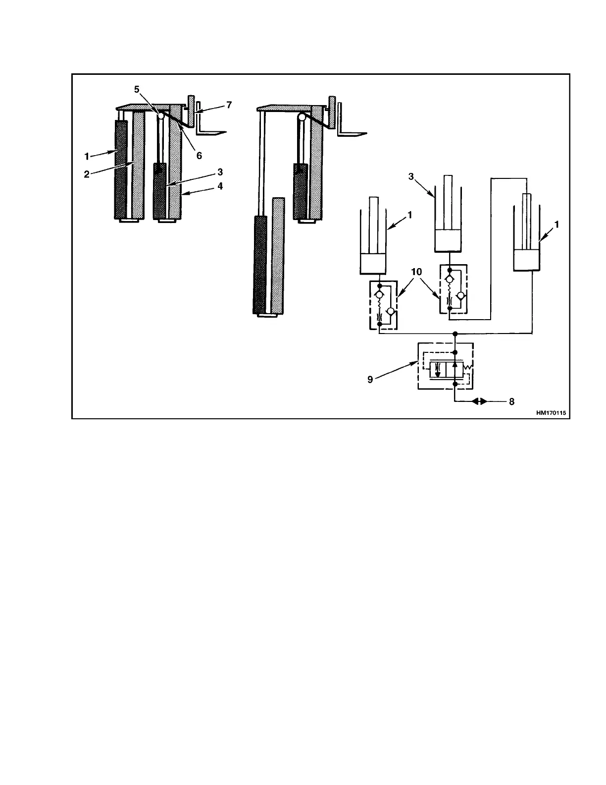
1. MAIN LIFT CYLINDER (2)
2. OUTER WELDMENT
3. FREE-LIFT CYLINDER
4. INNER WELDMENT
5. CHAIN SHEAVE
6. LIFT CHAIN
7. CARRIAGE
8. FROM MAIN CONTROL VALVE
9. EXTERNAL LOWERING CONTROL VALVE
10. INTERNAL LOWERING CONTROL VALVE
Figure 3. Two-Stage Mast With Full Free-Lift
During lowering, the main lift cylinders lower first
because they have a greater load. After the main lift
cylinders have retracted, the free-lift cylinder lowers.
All of the oil from the lift cylinders flows through the
lowering control valves to the hydraulic tank.
THREE-STAGE MAST WITH FULL
FREE-LIFT
The Vista Three-Stage mast has an outer, an inter-
mediate and an inner weldment. See Figure 4. Three
single stage lift cylinders are used on the mast to
raise the carriage and extend the weldments. The
weldments are telescopic and have load roller and
strip bearing arrangements similar to the two-stage
mast. The two main lift cylinders are installed at
the back of the outer weldment. The base of each lift
cylinder is held on a mount at the bottom of the outer
weldment. The hydraulic fittings for the lift cylin-
ders go through holes in the mounts. The top of each
main lift cylinder (cylinder rod) fits into a guide at
the top of the intermediate weldment. The free-lift
cylinder is installed in the inner weldment.
The two main lift chains fasten at one end near the
top of the outer weldment. The lift chains then go
over sheaves at the top of the intermediate weldment
and fasten at the bottom of the inner weldment. The
free-lift chains are connected to a mount behind the
free-lift cylinder. The chains then go over the sheaves
and connect to the carriage.
3