7-4
1. POWER CIRCUIT
The negative terminal of the battery is grounded to the machine chassis.
When the start switch is in the OFF position, the current flows from the positive battery terminal.
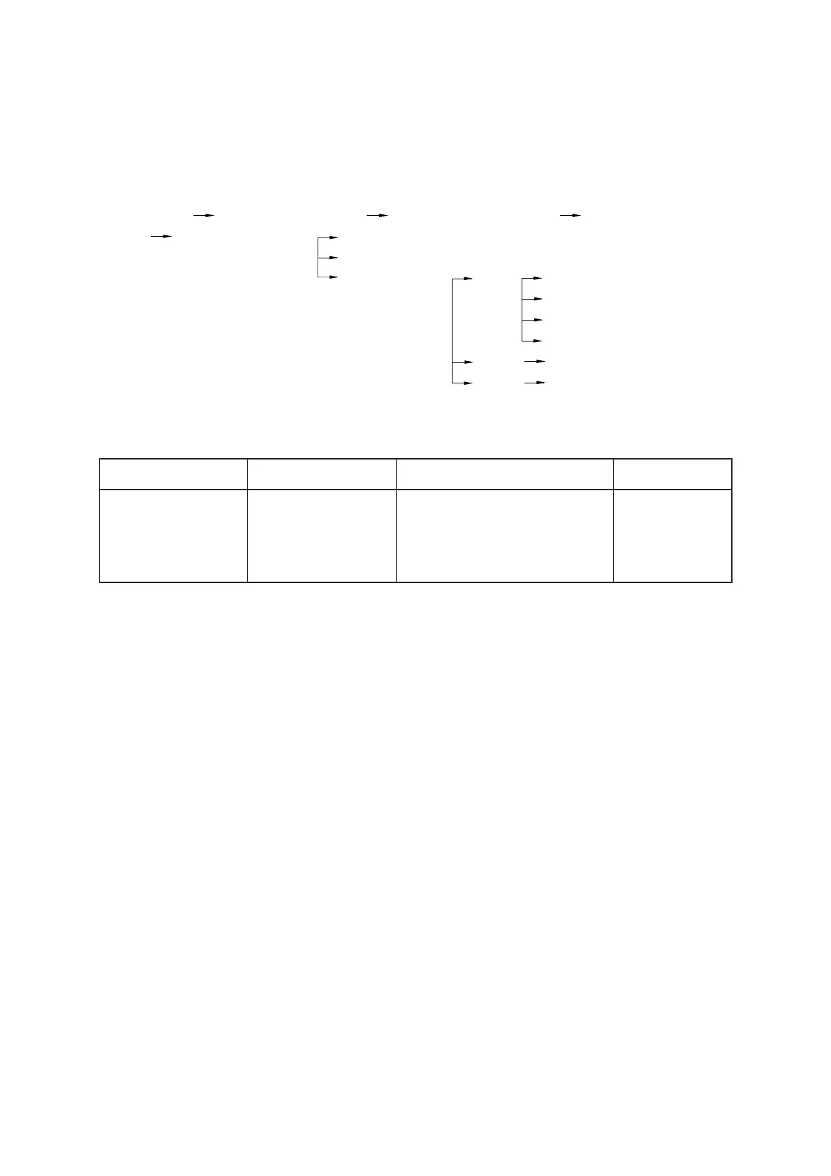
OPERATING FLOW
Battery(+) Start motor[CN-45(B+)] Fusible link[CN-95A(1
→
2)] Alternator[CN-74(B+)]
I/conn[CN-1(12,13,14) Start switch[CS-2(3)]
Start relay[CR-23(87)]
Fuse box[CN-36] (No.1) Cab[CN-7(1)]
OPSS buzzer[CN-113(2)]
Horn[CN-25(2)]
Brake switch[CD-4]
(No.2) Flasher unit[CR-11(2)]
(No.3) Opss unit[CN-55(12)]
1)
CHECK POINT
2)
Engine
OFF
Key switch
OFF
Voltage
10 ~ 13
V
Check point
①
- GND (Battery(+))
②
- GND (Fusible link)
③
- GND (Fuse No.1, 2, 3)
④
- GND (Start key)
 Loading...