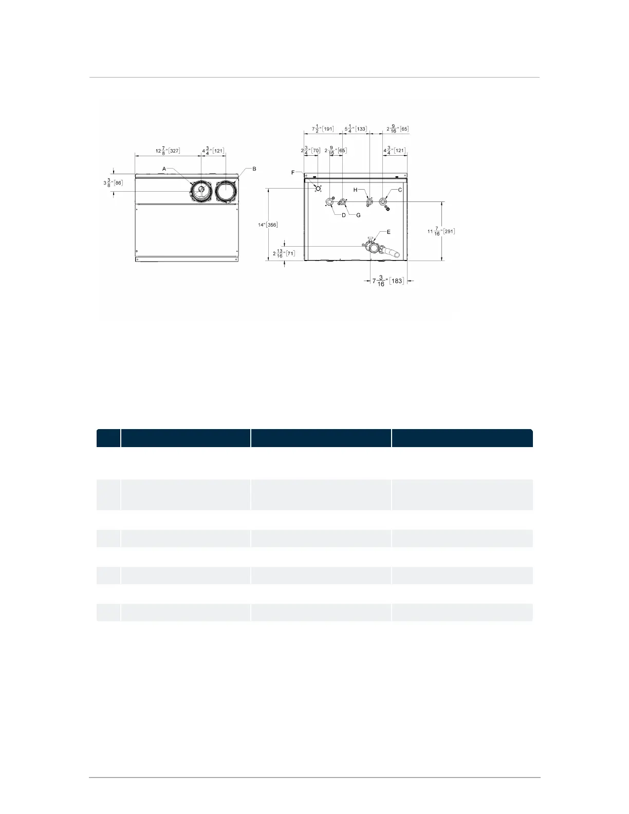
EasyManuals Logo
Home>IBC>Boiler>CX 150

IBC CX 150 User Manual

Default Icon
124 pages
To Next Page IconTo Next Page
To Previous Page IconTo Previous Page
Page #14 background imageLoading...
Page #14 background image
Figure 4 Top and bottom view - CX199
Connection specifications
The following table displays the required connection specifications.
Description CX150 CX199
A Flue Outlet 3" Schedule 40 or 3" PP (80
mm)
3" Schedule 40 or 3" PP (80
mm)
B Combustion Air Inlet 3" Schedule 40 or 3" PP (80
mm)
3" Schedule 40 or 3" PP (80
mm)
C Boiler Return Water Inlet 1" NPT-M 1" NPT-M
D Boiler Supply Water Outlet 1" NPT-M 1" NPT-M
E Condensate Outlet ¾" Hose ¾" Hose
F Gas Inlet ½" NPT-F ½" NPT-F
G DHW outlet (hot water) ¾" NPT-M ¾" NPT-M
H DHW inlet (cold water) ¾" NPT-M ¾" NPT-M
Table 1 Connections
14
Section: Specifications

Table of Contents

Other manuals for IBC CX 150

Questions and Answers:

Question and Answer IconNeed help?

Do you have a question about the IBC CX 150 and is the answer not in the manual?

IBC CX 150 Specifications

General IconGeneral
BrandIBC
ModelCX 150
CategoryBoiler
LanguageEnglish

Related product manuals