1. Disconnect and cap off the 120VAC leads connected to PV-L/PV-N
2. Provide 24VAC for the zone valves to the PVPower contacts on the Pump/ Zone Valve
terminal block
a. Use a separate transformer – the 40 VA appliance inside the wiring box is for internal
systems only
3. Wire individual load/zone valves to their associated contacts on the TB1 terminal strip
3.14.6 Thermostat heat anticipator
IBC “Therm” contacts draw no power, so an anticipator setting for the thermostat is not applicable
with these appliances. In the case of a single temperature / heat load where zone valves are used
to manage individual thermostatically controlled zones, each room thermostat’s heat anticipator
should be adjusted to the current draw of its associated zone valve.
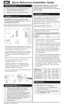
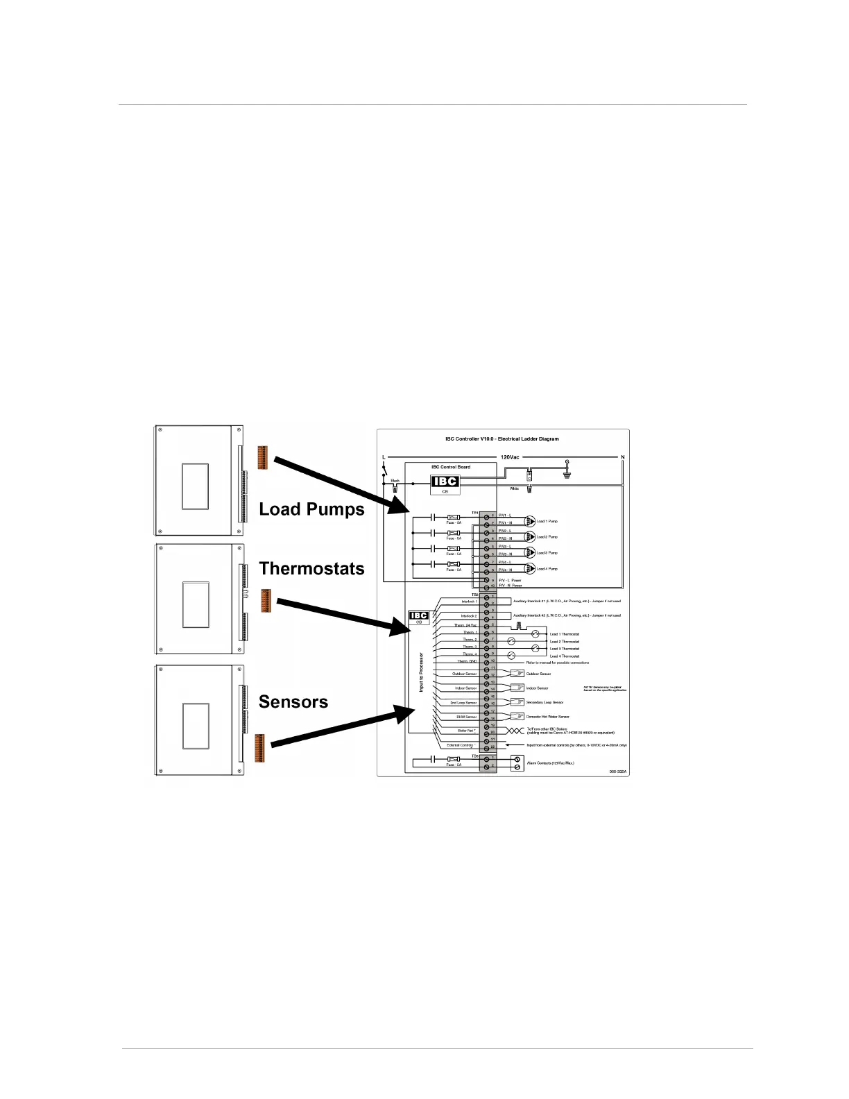
Figure 41 Electric wiring connections
3.14.6 Thermostat heat anticipator
 Loading...