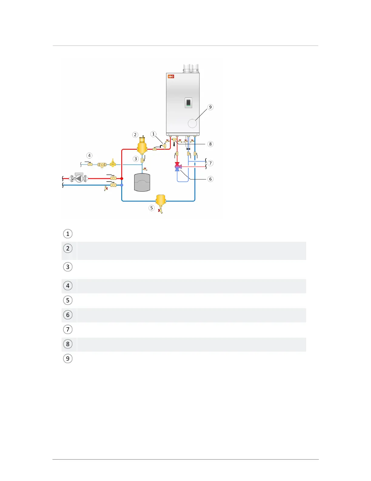
Isolation valve between boiler and relief valve not permitted
Microbubble air eliminators are best installed where the fluid is at the highest
temperature and lowest pressure
Expansion tank connection (point of no pressure change) should be on the suction
side of the circulator, with minimal pressure drop between.
Fill station with isolation valve closed, or fill tank.
Dirt separator recommended
Thermostatic tempering valve (if required by local code)
Domestic water
DHWrelief valve
Primary loop circulator built into return side of boiler
Figure 30 Boiler trim options - single boiler
Fluid fill is most often accomplished by using a boiler regulator and fill valve set at 12 psig or
more, with the appropriate backflow prevention device as required by local code. This is
acceptable in areas where municipal water or well water has been treated and filtered to
remove excessive minerals and sediment, and water chemistry is known to be suitable for