A ladder or step may be required to have a clear vertical view of the work area. Do not attempt
to reach from the front without a clear view, as damage to connectors, screws or refractory
may occur.
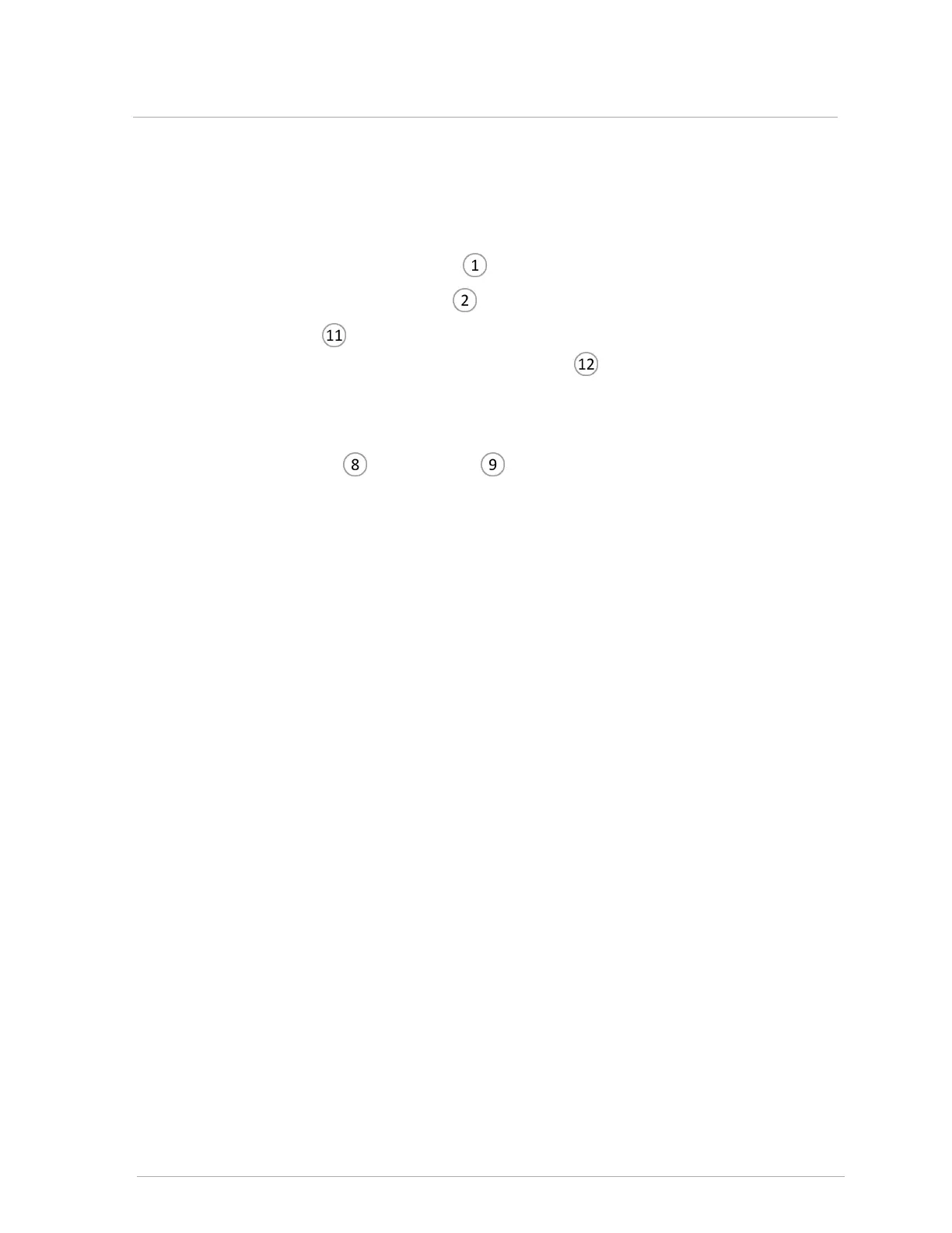
4. Remove the electrical connection to the gas valve with a Philips head screwdriver.
5.
Undo the union nut at the gas valve inlet .
6.
Carefully remove the gas valve gasket for re-installation.
7.
Undo the union nut connecting the gas valve outlet pipe to the mixer, and carefully remove
the gas valve/gas valve outlet pipe assembly and gasket from the combi boiler case. Set
the gasket aside for re-installation.
8. To detach the gas valve from the gas valve outlet pipe, undo the union nut at the gas valve
outlet, and set the pipe aside for re-installation.
9.
Ensure that the O-ring and nut retainer are secured to the pipe.
10. Attach the new gas valve on the gas valve outlet pipe, tightening the union nut on the gas valve
outlet with the nut retainer and O-ring in place.
11. Reinstall the components in reverse order. Upon reassembly, ensure that all O-rings and
gaskets are correctly positioned.
12. Before restoring the combi boiler to normal operation, check for leaks at the gas valve inlet .
13. With the combi boiler operating, check for leaks at the gas valve outlet.
14. Tune the gas valve. For instructions, see Adjusting the gas valve on page 78.
15. After removing test equipment check test ports and replace door.
7.3.2 Replacing the gas valve