INSTALLATION AND OPERATION INSTRUCTIONS
1-4
SL 10-85 G3, SL 14-115 G3, SL 20-160 G3, SL 30-199 G3 MODULATING GAS BOILERSSL 10-85 G3, SL 14-115 G3, SL 20-160 G3, SL 30-199 G3 MODULATING GAS BOILERS
SURFACE
DISTANCE FROM
COMBUSTIBLE
SURFACES
RECOMMENDED DISTANCE
FOR INSTALLATION AND
SERVICE
Front 2” 24”
Rear 0” 0”
Left Side 1”
4” (allow access to water
connections)
Right Side 1”
4” (water, electric and gas
connections)
Top 2” 6” (for vent connection)
Bottom 0” 12” (for condensate trap)
Table 2 - Clearance from boiler cabinet
A minimum distance below the boiler of 12” is required to provide clearance for the
supplied condensation trap assembly. More clearance will typically be required to
accommodate associated water and gas piping.
1.4 EXHAUST VENTING & AIR INTAKE
It is important to carefully plan the installation to ensure the appropriate vent materials,
travel and termination decisions are included. Specic attention is warranted to manage
the impact of the steam plume normally experienced at the exhaust terminal of a
condensing boiler. Generally, intake and exhaust pipes should terminate at a rooftop or
sterile wall location, to maximize customer satisfaction. Keep exhaust plumes well away
from all building air intakes including those of neighboring properties.
All venting must be installed in accordance with the requirements of the jurisdiction having
authority: in Canada, Part 8, Venting Systems of the B149.1-10 Code and any other local
building codes are to be followed. In the USA the National Fuel Gas Code, ANSI 223.1,
latest edition, prevails. Where there is a discrepancy between the installation instructions
below, and the code requirements, the more stringent shall apply.
IMPORTANT
When an existing boiler is removed from a common venting system, the common venting
WARNING
Ensure that combustible
materials do not make contact
with exposed water piping
and associated components
(relief valves, circulators, etc.).
Check local codes for required
clearances and/or provide
adequate insulation.
DANGER
Do not common vent the SL
modulating series boilers
with any other existing or new
appliance.
WARNING
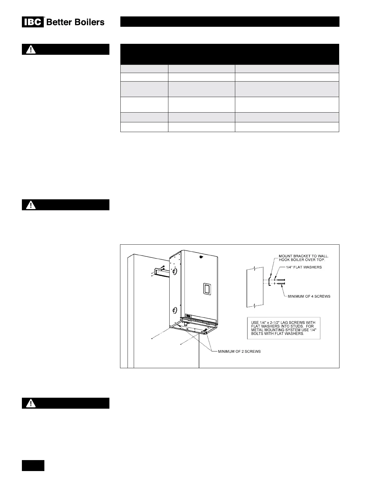
DO NOT MOUNT THIS
BOILER TO HOLLOW WALL
STRUCTURES - The combined
weight of the boiler, its water
contents and associated piping
components can exceed 150
pounds. Fasteners must be rated
for this strain, and must be rmly
anchored into solid material that
will support this weight.
Installers are to take all
necessary precautions to avoid
injury during the installation of
this boiler.
Figure 3: Wall mounting of boiler
 Loading...


