INSTALLATION AND OPERATION INSTRUCTIONS
4-4
SL 10-85 G3, SL 14-115 G3, SL 20-160 G3, SL 30-199 G3 MODULATING GAS BOILERS
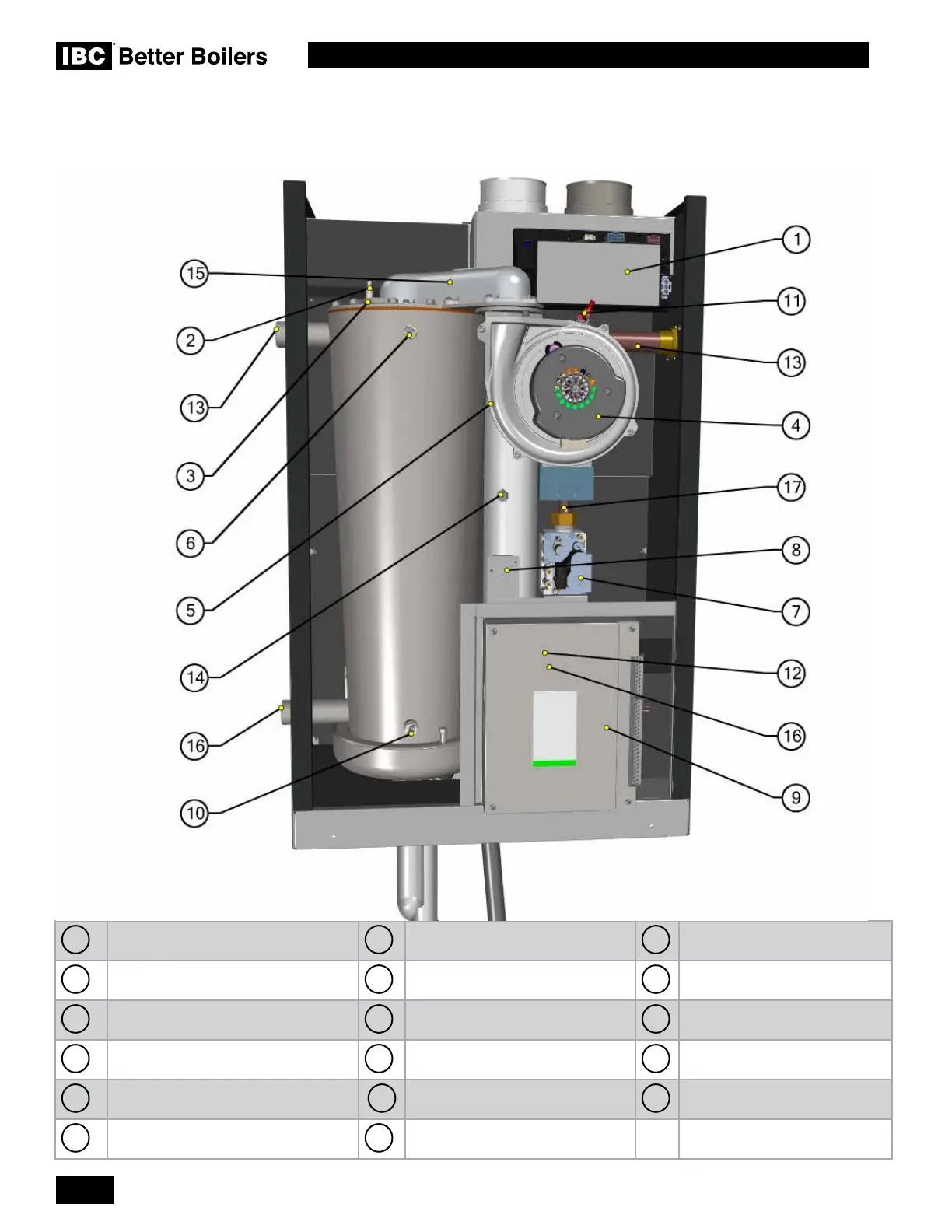
4.2 GEOGRAPHY & COMPONENTS
1
Safety Ignition Module
7
Gas Valve
13
Supply Water Pipe
2
Ignitor
8
Air pressure switch (behind
bracket)
14
Combustion Test Port
3
Site Glass
9
Touchscreen controller
15
Fan Coupler
4
Combustion Fan
10
Return Water Temperature Sensor
16
Return Water Pipe (behind - on
the right side)
5
Flue Gas Temperature Sensor (behind
the combustion fan)
11
Low Water Cutoff Probe
17
Gas Tube
6
Supply Water Temperature Sensor
12
Water Pressure Sensor (behind
the touchscreen controller)
 Loading...


