1-1
INSTALLATION
SL 10-85 G3, SL 14-115 G3, SL 20-160 G3, SL 30-199 G3 MODULATING GAS BOILERS
1.0 INSTALLATION
1.1 GENERAL
SL Series gas-red modulating boilers are low pressure, fully condensing units having
variable input ranges (see specication chart - inside, front cover). Approved as “Category
IV” vented appliances, the boilers use either Direct Vent (sealed combustion) or indoor
combustion air, providing a great degree of installation exibility.
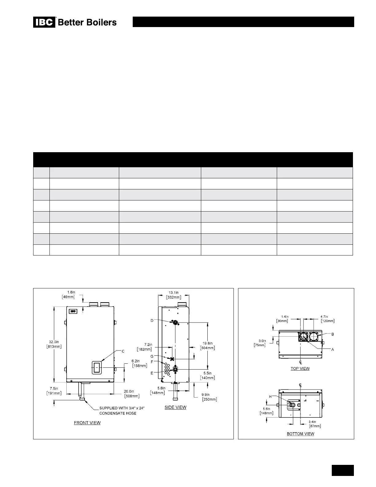
Figures 1a,and 1b show outer case dimensions and piping and electrical holes. Refer to
the applicable diagrams to help nd a suitable location for the boiler. See also Section 1.3
Location.
Figure 1: Dimensions / Connections for SL SL 10-85 G3/ SL 14-115 G3 - Front view, side view, top view and bottom view
DESCRIPTION
SL 10-85 G3/
SL 14-115 G3
SL 20-160 G3
SL 30-199 G3
A Exhaust Outlet 3” Schedule 40 3” Schedule 40 3” Schedule 40
B Combustion Air 3” Schedule 40 3” Schedule 40 3” Schedule 40
C LCD Display 2-1/4” x 4” 2-1/4” x 4” 2-1/4” x 4”
D Water Outlet 1” NPT-M 1” NPT-M 1-1/4” NPT-M
E Water Inlet 1” NPT-M 1” NPT-M 1-1/4” NPT-M
F Knock-outs (8) 1/2” 1/2” 1/2”
G Gas Inlet 1/2” NPT-F 1/2” NPT-F 1/2” NPT-F
H Condensate Outlet 3/4” Hose 3/4” Hose 3/4” Hose
Table 1: Connections
 Loading...


