1-21
INSTALLATION
SL 10-85 G3, SL 14-115 G3, SL 20-160 G3, SL 30-199 G3 MODULATING GAS BOILERSSL 10-85 G3, SL 14-115 G3, SL 20-160 G3, SL 30-199 G3 MODULATING GAS BOILERS
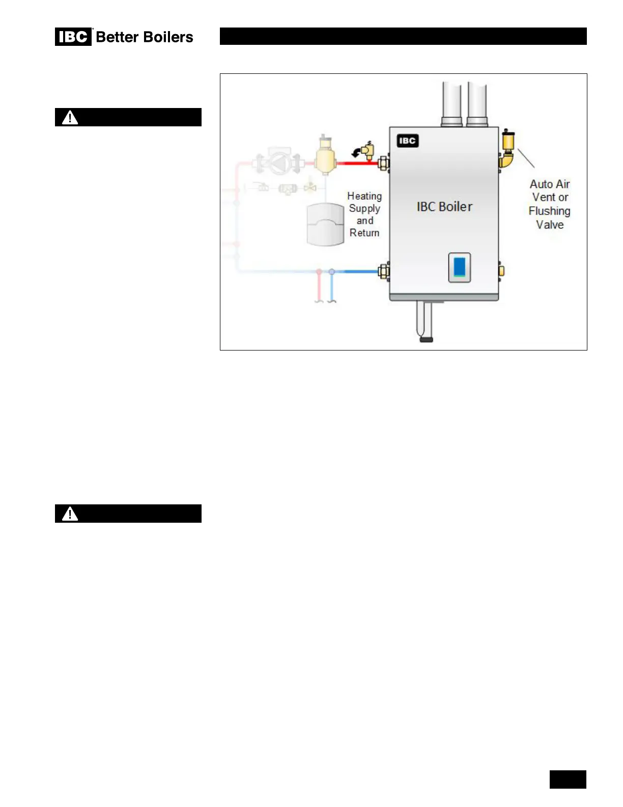
Figure 27: Consideration for left-side only piping
Note that the supply pipe off the right-hand side of the heat exchanger carries the LWCO
device. If all heating loads are on the left-hand side only, ensure that the right-hand supply
connections use an auto air vent or a ushing valve.
The SL modulating series boilers are designed for use within a closed loop, forced
circulation, low pressure system. A 30 psi pressure relief valve (3/4” NPT) is supplied for
eld installation at one of the locations shown in the following illustrations. Relief valve
discharge piping must terminate between 6” (15cm) and 12” (30cm) above the oor or per
local Code.
Due to the various piping options available, positioning the pressure relief valve can vary.
When piping from either side, the relief valve is installed in the upper port opposite the
supply outlet, using the ttings provided (see Figure 30).
If piping from both sides at the same time, a tee must be installed on either supply outlet,
immediately on exiting the boiler so that there is no possibility of installing an isolation
valve between the pressure vessel and the relief valve.
CAUTION
Installers should inquire of
local water purveyors as to the
suitability of their supply for use
in hydronic heating systems.
If water quality is questionable,
a local water treatment expert
must be consulted for testing,
assessment and, if required,
treatment.
Alternatively, water or hydronic
uid of known quality can be
brought to the site.
WARNING
During operation, the relief valve
may discharge large amounts
of steam and/or hot water.
Therefore, to reduce the potential
for bodily injury and property
damage, a discharge line MUST
be installed that it:
1. is connected from the valve outlet
with no intervening valve and
directed downward to a safe point of
discharge.
2. allows complete drainage of both the
valve and the discharge line.
3. is independently supported and
securely anchored so as to avoid
applied stress on the valve.
4. is as short and straight as possible
5. terminates freely to atmosphere
where any discharge will be clearly
visible and is at no risk of freezing.
6. terminates with a plain end which is
not threaded.
7. is constructed of a material suitable
for exposure to temperatures of
375°F or greater.
8. is, over its entire length, of a pipe size
equal to or greater than that of the
valve outlet.
DO NOT CAP, PLUG OR OTHERWISE
OBSTRUCT THE DISCHARGE PIPE
OUTLET!
 Loading...


