1-23
INSTALLATION
SL 10-85 G3, SL 14-115 G3, SL 20-160 G3, SL 30-199 G3 MODULATING GAS BOILERS
System piping is connected to the boiler using the 1” NPT Male threaded ttings on the
right or left side connection ports. Unions and gate or ball valves at the boilers supply and
return water connections are recommended to simplify servicing. Un-insulated hot water
pipes must be installed with a minimum 1” clearance from combustible materials.
Fluid ll is most often accomplished by using a boiler regulator & ll valve set at 12 psig
or more, with the appropriate backow prevention device as required by local code. This
is acceptable in areas where municipal water or well water has been treated and ltered
to remove excessive minerals and sediment, and water chemistry is known to be suitable
for closed loop hydronic systems. In areas where water quality is in question, or when
chemical treatment or glycol is required, other options should be considered. Follow
applicable codes and good piping practice.
There are a number of boiler feed and pressurization devices on the market today that
may be a better choice than a raw water ll from the mains. When regular maintenance
requires relief valve blow-off, the discharge may be directed back into the pressurization
unit for recycling of boiler uid and chemicals back into the system. In buildings that may
be unoccupied for long periods of time, pressurization units are useful to prevent ood
damage should leakage occur from any component in the system. An additional benet is
that backow prevention devices are not required when using these devices.
Do not place any water connections above the boiler. Leaks can damage the fan and
controls. If needed, create a shield over the top of the cover, but allow clearance for airow
and service access.
For best results regarding the SL 14-115 G3, use a Primary/Secondary piping system with
a pumped boiler loop (using 1” piping). Heat exchanger head is only 1.5’ at 4 USgpm and
approximately 4’ at 10 USgpm.
The minimum ow rate required through the heat exchanger is listed in Tables 5A and 5B.
Primary/Secondary piping ensures adequate ow and de-couples Δ°T issues (boiler vs.
distribution). Aim for a 20° to 30° F Δ°T across the heat exchanger at high re (there is a
boiler protection throttle fence limiting the Δ°T to 40°F).
Propylene glycol solution is commonly used in a closed loop where freeze protection is
required. Its density is lower than that of water, resulting in lower thermal performance at a
given ow and pressure. As a rule of thumb, a 50%:50% solution of propylene glycol and
water will require an increased system circulation rate (gpm up 10%), and system head
(up 20%) to provide performance equivalent to straight water.
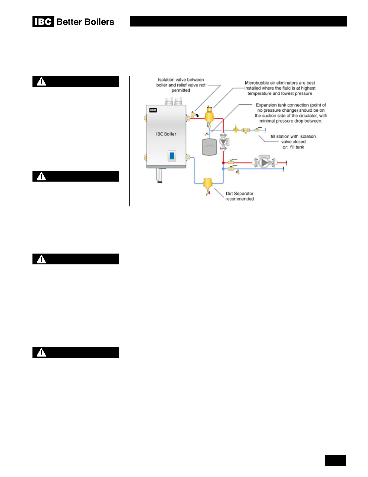
Figure 30: Boiler trim basic options
WARNING
Close ll valve after any addition
of water to the system, to reduce
risk of water escapement.
NOTE
Full sized application drawings
can be downloaded from our web
site.
www.ibcboiler.com
NOTE
The boiler, when used in
connection with a refrigeration
system, must be installed so
the chilled medium is piped
in parallel with the boiler with
appropriate valves to prevent the
chilled medium from entering the
boiler.
NOTE
The boiler piping system of a hot
water boiler connected to heating
coils located in air handling units
where they may be exposed to
refrigerated air circulation must
be equipped with ow control
valves or other automatic means
to prevent gravity circulation
of the boiler water during the
cooling cycle.
 Loading...


