6-9
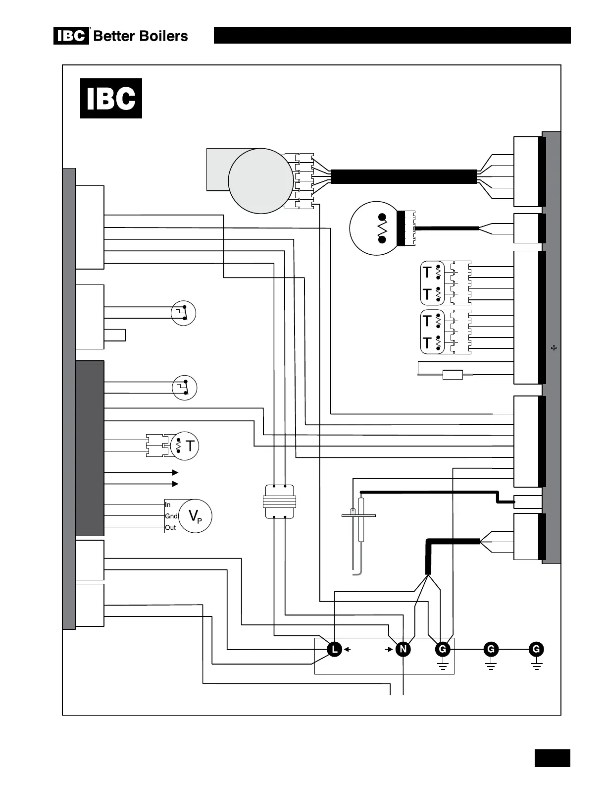
DIAGRAMS
SL 10-85 G3, SL 14-115 G3, SL 20-160 G3, SL 30-199 G3 MODULATING GAS BOILERS
Diagram 6.2-2: Internal wiring diagram
Better
Boilers
orange
white
17
16
24 Vac
120 Vac
green
red
red
yellow
white
white
blue
blue
white
green
black
black
blue
green
green
TB1
10
9
Flue Gas
Temperature
Sensor
100-029A
Mains
Power Supply
Electrode
and Flame
Sensing Rod
Assembly
Spark
black
black
yellow
red
white
black
VS Out 0-10VDC
SL 14-115G3, SL 20-160G3, SL 20-199G3
Replacement internal wiring
must meet or exceed the
ratings of the wiring supplied
from the factory.
green
Transformer
green
green
green
green
green
black
Upper Vessel
High Limit
Switch
white
yellow
white
red
white
white
yellow
brown
black
blue
orange
orange
blue
Inlet Water
Pressure
Sensor
white
white
black
yellow
To Boiler Pump
green green
Grounded
to case
Inlet Water
Temperature
Sensor
Outlet Water
Temperature
Sensor
2 x plug
red
10
9
15
2
1
1
1
2
3
4
22
13
27
28
6
4
5
120Vac
LWCO Probe
INTERNAL WIRING DIAGRAM
IBC Control Board
P 102
P 101
P3
6
P 702
5
white
white
IBC SIM Module
+
3
4
4
2
2
2
2
1
1
1
P2
P303
P301
P5
7
5
3
8
6
1
9
2
3
4
5
6
7
8
9
11
T1b
orange
red
white
orange
white
white
blue
red
brown
brown
white
black
black
33
24
white
P 501
orange
4 x plug 4 x plug
Exhaust
Pressure
Switch
Combustion
NRG130
Fan
Gas
Valve
5 x plug
6
1
2
3
4
5
Bn
Bk
SIM-J2 J2 - Sensor Inputs SIM-J5Fan 120V Fan Drive
 Loading...


