EasyManua.ls Logo

IBC V-10 User Manual

IBC V-10
103 pages
To Next Page IconTo Next Page
To Previous Page IconTo Previous Page
Page #27 background imageLoading...
Page #27 background image
If using Setup, load priority is simplified with options "very low",
"low", "high" or "very high". There's more precision in Advanced
Setup, where you can enter numeric values between 20 and 90 for
a priority load. Note: The priority value has to be different for each
load, but the priority scale values do not need to add up to 100
they are relative only to each other. A higher numerical value
means a higher priority.
Consider priority values as minutes. The difference between two
load priority values is the number of minutes the higher priority
load will operate before switching back to the lower priority load.
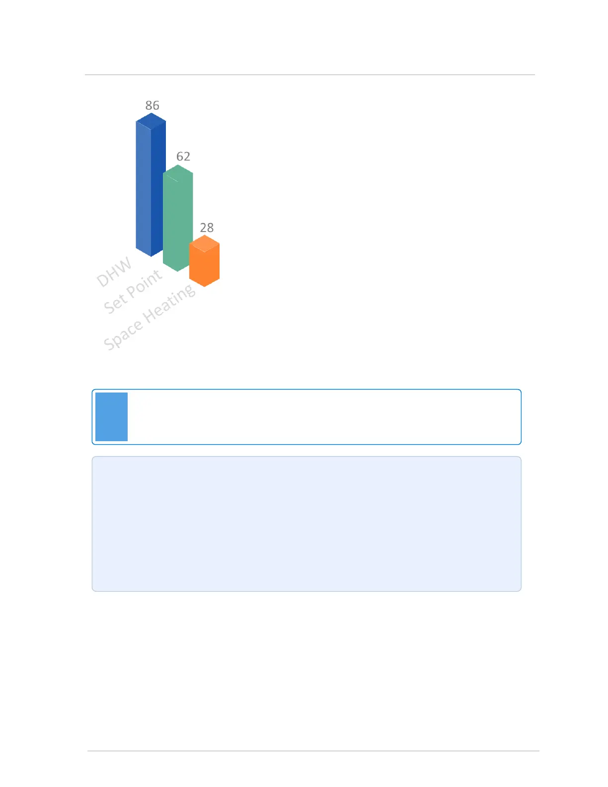
For example, if DHW has a priority of 86 and the Set Point load
has a priority of 62, the DHW load will run for (86-62) 24 minutes
before switching to the simultaneously calling Set Point load.
Following the initial cycle, the competing loads will switch back
and forth after a further 10-minute interval pending satisfaction of
one or both loads.
Figure 10 Default priority values by load type in Installer Settings
Note
Ensure that loads are set with a minimum of 15-minute differential between competing
loads.
Example: If baseboards (set up with Reset Heating as Load 3) are not providing the desired
heat, you can bring on baseboard run time sooner by increasing the priority value relative to the
other declared loads (e.g., changing the Load 3 preset value from 43 to 50 or reducing another
load’s value). Temperature targets for the under-served load can also be raised, in this
example.
To cause repeated unequal run times; for example, constant 35 vs 5-minute runs, you need to
integrate an external load removing relay or timer on one of the heat calls. Do not set each load
to the top value, and avoid equal ratings.
25
2.6 Setting load priority

Table of Contents

Other manuals for IBC V-10

Questions and Answers:

IBC V-10 Specifications

General IconGeneral
BrandIBC
ModelV-10
CategoryController
LanguageEnglish

Summary

1.0 Overview of the controller

1.1 Controller's menu screens

Diagrams the controller's four main menus and their associated submenus.

1.3 Power-up sequence and operational states/cycles

Details the controller's five operational states and error detection.

1.4 Getting to know the controller’s interface

Explains the main screen menus: Home, Setup, Status, and More.

2.0 Operating concepts

2.1 Domestic hot water (DHW)

Explains the controller's priority for DHW service and its operation.

2.2 Reset heating

Describes balancing building heat loss with supplied heat via temperature adjustments.

2.3 Set Point

Defines set point as controller temperature, not room thermostat reading.

2.4 External Control

Details controlling the boiler via an external electronic controller or BMS.

2.6 Setting load priority

Explains the priority algorithm for coordinating heat delivery in multi-load systems.

2.7 Combining loads

Describes combining compatible loads for simultaneous operation for efficiency.

2.8 Setting the supply differential in heating modes

Explains using differential to prevent short cycling and maintain boiler efficiency.

2.9 Operational settings in the Setup menu: temperature ranges and defaults

Lists default operational settings for DHW, Reset Heating, Setpoint, and Ext. Control.

2.10 Operational settings in the Advanced Setup menu: temperature ranges and defaults

Provides advanced operational settings for various modes and parameters.

3.0 Wiring

3.1 Boiler pump

Details wiring the boiler pump to its harness lead for VX series boilers.

3.2 Thermostats

Explains compatibility with common thermostats and wiring connections.

3.3 Load pumps or valves

Describes wiring up to four load pumps to the load pump terminals.

3.4 Sensors

Details wiring thermistors for Outdoor, Indoor, 2nd Loop, and DHW sensors.

3.7 Multiple boilers: wiring and networking

Covers connecting and networking multiple IBC boilers for energy savings.

3.8 Wiring checklist

Provides checks to confirm successful wiring of the boiler system.

4.0 Settings loads

4.1 Configuring loads using Setup (recommended)

Provides a quick method for setting parameters for most single-boiler installations.

4.2 Setting loads using Advanced Setup

Offers more options for experienced installers to configure loads.

4.3 Setting up an external control load

Details setting up external control for BMS to manage boiler set points.

4.5 Combining two loads to service two loads at the same time

Explains combining loads using basic or full mode for simultaneous operation.

5.0 Configuring multiple boiler systems

5.2 Configuring a master boiler

Assigns a boiler as the 'master' to control subordinate boilers on the network.

5.3 Configuring a subordinate boiler

Details basic configuration for subordinate boilers controlled by the master.

5.8 Setting up an IBC air handler to send data to an IBC boiler to control its reset heating curve

Configures communication for air handler data to control boiler reset curves.

6.0 Start-up

6.1 Start-up checklist

Lists essential checks before energizing the boiler for the first time.

6.2 Testing the ignition safety shutoff

Procedure to verify the ignition system's safety shutoff functionality.

6.3 Testing the Hi-limit temperature function

Tests the maximum supply cutoff temperature function of the boiler.

6.4 Testing the low water cutoff (LWCO) function

Verifies the LWCO function for protection against low water incidents.

7.0 Optional - Setup for Internet access

7.1 Connecting a boiler’s controller to an IP network

Details connecting the controller to an IP network for web browser capability.

8.0 Updating boiler controller software

8.1 Updating software in a boiler that has no internet access

Outlines the three stages for updating software without internet connectivity.

8.2 Updating software in a boiler that has internet access

Describes the process of updating software using a USB drive or SD card.

9.0 Other operating procedures

9.1 Testing the fan operation

Tests the fan's heat output and includes vent factor analysis.

9.2 Testing the firing rate

Allows testing the firing rate if the fan is not operating or if there are airflow errors.

9.3 Calibrating the fan

Required procedure after replacing a fan or performing a software update.

9.5 Limiting the minimum and maximum firing rate of the boiler

Adjusts boiler output for oversized installations or low-wind environments.

9.9 Setting overrides

Enables setting up automated temperature overrides for specific loads like DHW.

9.10 Backing up and restoring a boiler's configuration and settings

Allows saving and loading controller configuration and settings via USB/SD.

9.13 Resetting configured settings to factory defaults

Resets all boiler settings to default for troubleshooting or configuration reset.

9.18 Programming a replacement touchscreen controller

Guides on entering correct boiler details after installing a new controller.

10.0 Troubleshooting

10.1 Viewing errors

Accesses the Error Logs screen to view detailed information about present errors.

10.2 Clearing errors

Resets error states and forces the controller to reassess the boiler's status.

10.3 List of touchscreen controller error messages

Provides a list of encountered error messages and diagnostic steps.

Appendices

Internal wiring diagram VX series boilers

Illustrates the internal wiring connections for VX series boilers.

Wiring diagram - Opt Out DHW

Provides a specific wiring diagram for DHW opt-out applications.

Sequence of Operation - VX series boilers

Details the operational flow and sequence for VX series boilers.

Related product manuals