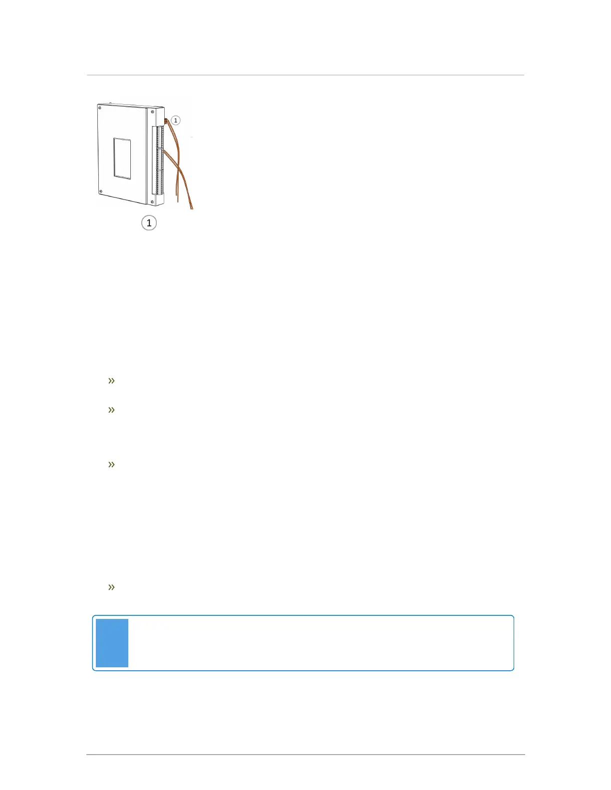
Figure 13 : Field wiring box with yellow and white wires for primary pump - VX series
3.2 Thermostats
The controller is compatible with most common thermostats including simple single contact types
(for example, a mercury switch) as well as most power-stealing-type thermostats. The standard
connection for common thermostats provides a simple contact closure for the boiler (see the
electrical diagrams in the Appendices on page 93). For example, Therm 1 will activate Pump 1,
Therm 2 will activate Pump 2, etc (see Figure 12 ) .
The Therm. 24Vac (TB2 terminal 5) provides 24 volts AC to all thermostats (up to four). This
connects to the "R" terminal on the thermostat.
Each individual thermostat’s "W" terminal connects separately to one of the controller input
terminals: Therm. 1 (TB2: 5-6); to activate load one, close 5-6, Therm. 2 (TB2: 5-7); to
activate load 2, close 5-7, Therm. 3 (TB2: 5-8); to activate load 3, close 5-8, or Therm. 4
(TB2: 5-9); to activate load 4, close 5-9.
Power stealing thermostats take a small amount of current from the 24VAC to operate their
internal electronics. To complete the 24VAC circuit required to operate power stealing
thermostats, the controller includes an internal 2740 ohm resistor from the thermostat input
to ground.
This internal resistor limits the power available to the thermostat and for some models
additional power is required for proper operation. Thermostats that require this extra amount
of power (for example the Honeywell T8775) will have a resistor available from the
manufacturer capable of supplying the required power.
Connect the power resistor from the thermostat’s input terminal to the Therm. GND (TB2-10)
terminal.
Note
Some thermostats, for example those with WiFi circuits, may require their own 24V
power source.