2
The
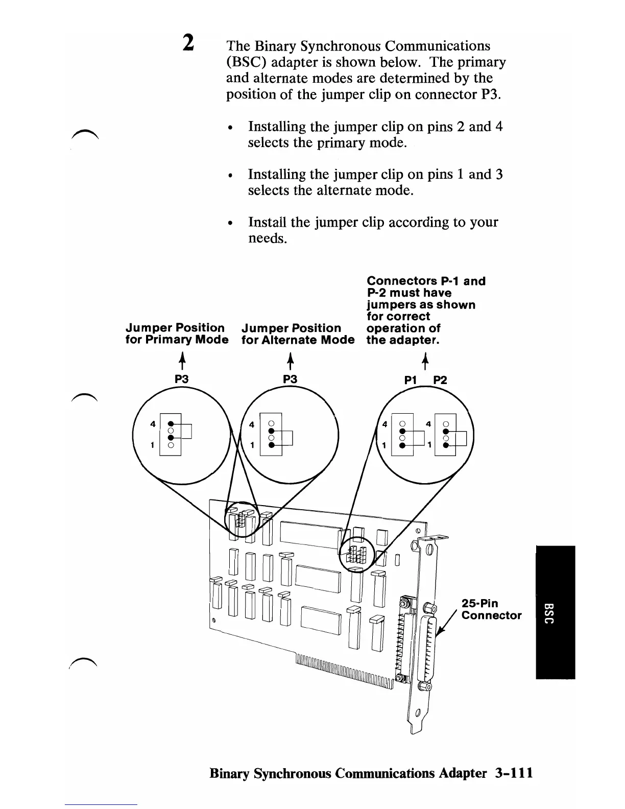
Binary Synchronous Communications
(BSC)
adapter
is shown below.
The
primary
and
alternate modes are determined
by
the
position
of
the
jumper clip
on
connector P3.
• Installing the jumper clip
on
pins 2
and
4
selects the primary mode.
• Installing the jumper clip
on
pins 1 and 3
selects the alternate mode.
• Install the jumper clip according
to
your
needs.
Connectors
P·1
and
P·2
must
have
jumpers
as
shown
for
correct
Jumper
Position
Jumper
Position
operation
of
for
Primary
Mode
for
Alternate
Mode
the
adapter.
+ + +
P3 P3
P1
P2
Binary Synchronous Communications Adapter 3-111