Adapter FRU number
00E3496 (Designed to comply with RoHS requirement)
Wrap plug FRU number
12R9314
I/O bus architecture
PCIe3 x8
Slot requirement
For more information about slot priorities, maximums, and placement rules, see PCIe adapter
placement rules and slot priorities (http://www.ibm.com/support/knowledgecenter/POWER9/
p9eab/p9eab_mtm_pciplacement.htm) and select the system that you are working on.
Voltage
3.3 V, 12 V
Form factor
Short, low-profile
FC compatibility
4, 8, 16 Gb
Cables
Cables are the responsibility of the customer. Use multimode fiber optic cables with shortwave
lasers that adhere to the following specifications:
v OM4: Multimode 50/125 micron fiber, 4700 MHz x km bandwidth
v OM3: Multimode 50/125 micron fiber, 2000 MHz x km bandwidth
v OM2: Multimode 50/125 micron fiber, 500 MHz x km bandwidth
v OM1: Multimode 62.5/125 micron fiber, 200 MHz x km bandwidth
Because core sizes are different, OM1 cables can only be connected to other OM1 cables. For best
results, OM2 cables must not be connected to OM3 cables. However, if an OM2 cable is connected
to an OM3 cable, the characteristics of the OM2 cable apply to the entire length of the cables.
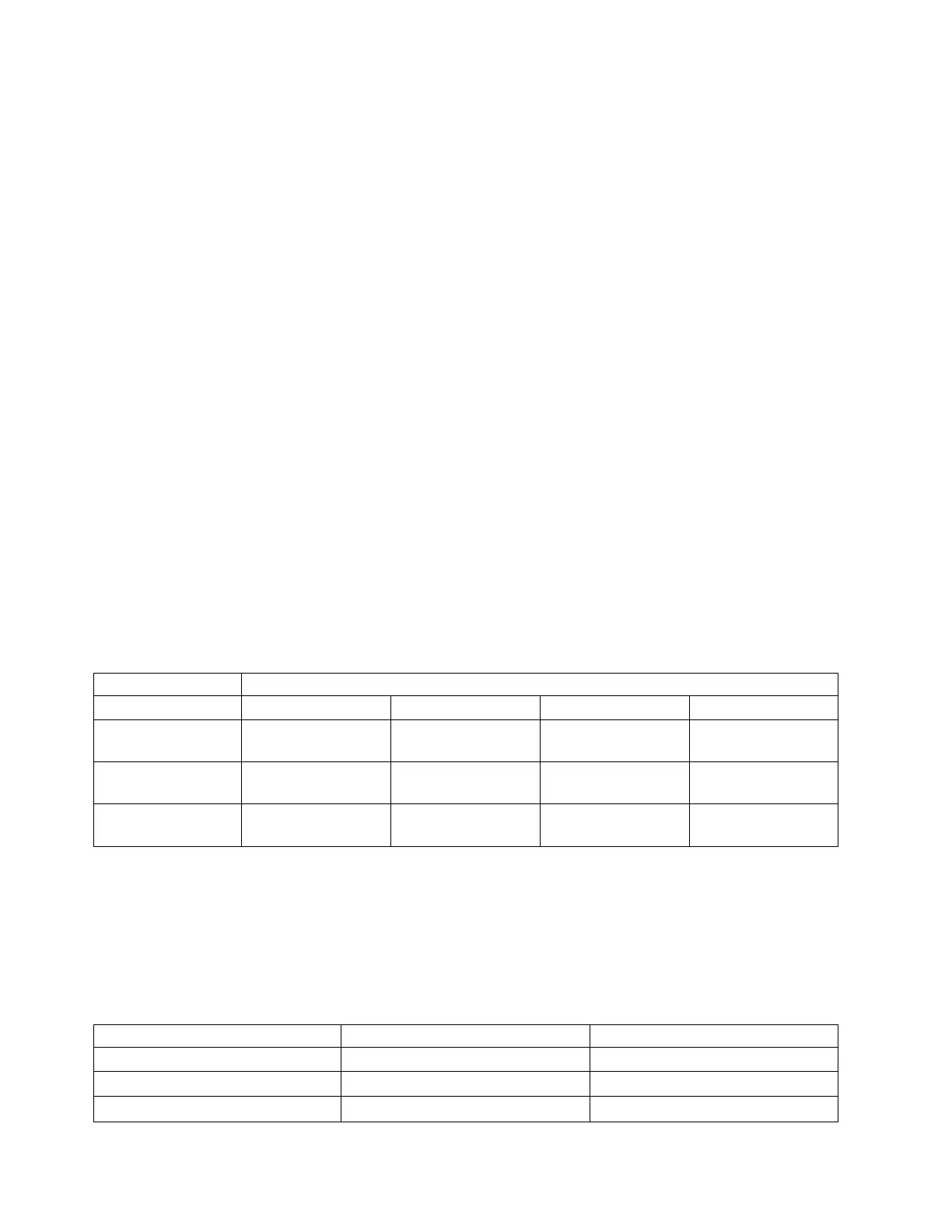
The following table shows the supported distances for the different cable types at the different
link speeds.
Table 34. Supported distances for cables
Header Cable type and distance
Rate OM1 OM2 OM3 OM4
4.25 Gbps 0.5 - 70 m (1.64 -
229.65 ft)
0.5 - 150 m (1.64 -
492.12 ft)
0.5 - 380 m (1.64 -
1246.71 ft)
0.5 - 400 m (1.64 -
1312.34 ft)
8.5 Gbps 0.5 - 21 m (1.64 -
68.89 ft)
0.5 - 50 m (1.64 -
164.04 ft)
0.5 - 150 m (1.64 -
492.12 ft)
0.5 - 190 m (1.64 -
623.36 ft)
14.025 Gbps 0.5 - 15 m (1.64 -
49.21 ft)
0.5 - 35 m (1.64 -
114.82 ft)
0.5 - 100 m (1.64 -
328.08 ft)
0.5 - 125 m (1.64 -
410.10 ft)
Adapter LED states
Green and yellow LEDs can be seen through openings in the mounting bracket of the adapter. Green
indicates firmware operation, and yellow signifies port activity. Table 35 summarizes normal LED states.
A 1 Hz pause occurs when the LED is off between each group of fast flashes (2, 3 or 4). Observe the LED
sequence for several seconds to ensure that you correctly identify the state.
Table 35. Normal LED states
Green LED Yellow LED State
On 2 fast flashes 4 Gbps link rate: normal, link active
On 3 fast flashes 8 Gbps link rate: normal, link active
On 4 fast flashes 16 Gbps link rate: normal, link active
122 Managing PCIe adapters
 Loading...