7.9.11 Page 0C (Notch Parameters)
ÚÄÄÄÄÄÄÄÄÄÄÄÄÄÄÄÄÄÄÄÄÄÄÄÄÄÄÄÄÄÄÄÄÄÄÄÄÄÄÄÄÄÄÄÄÄÄÄÄÄÄÄÄÄÄÄÄÄ¿ ÚÄÄÄÄÄÄÄÄÄ¿
³
BIT
³³ ³
³
76543210
³³
Default
³
ÚÄÄÄÄÄÄÄÅÄÄÄÄÄÄÂÄÄÄÄÄÄÄÂÄÄÄÄÄÄÄÄÄÄÄÄÄÄÄÄÄÄÄÄÄÄÄÄÄÄÄÄÄÄÄÄÄÄÄÄÄÄÄÄÄÄ´ ÃÄÄÄÄÄÄÄÄÄ´
³
BYTE 0
³
PS
³
RSVD=0
³
Page Code = 0Ch
³³
8Ch
³
ÃÄÄÄÄÄÄÄÅÄÄÄÄÄÄÁÄÄÄÄÄÄÄÁÄÄÄÄÄÄÄÄÄÄÄÄÄÄÄÄÄÄÄÄÄÄÄÄÄÄÄÄÄÄÄÄÄÄÄÄÄÄÄÄÄÄ´ ÃÄÄÄÄÄÄÄÄÄ´
³
BYTE 1
³
Page Length = 16h
³³
16h
³
ÃÄÄÄÄÄÄÄÅÄÄÄÄÄÄÂÄÄÄÄÄÄÄÂÄÄÄÄÄÄÄÄÄÄÄÄÄÄÄÄÄÄÄÄÄÄÄÄÄÄÄÄÄÄÄÄÄÄÄÄÄÄÄÄÄÄ´ ÃÄÄÄÄÄÄÄÄÄ´
³
BYTE 2
³
ND=1
³
LPN=0
³
RSVD = 0
³³
80h
³
ÃÄÄÄÄÄÄÄÅÄÄÄÄÄÄÁÄÄÄÄÄÄÄÁÄÄÄÄÄÄÄÄÄÄÄÄÄÄÄÄÄÄÄÄÄÄÄÄÄÄÄÄÄÄÄÄÄÄÄÄÄÄÄÄÄÄ´ ÃÄÄÄÄÄÄÄÄÄ´
³
BYTE 3
³
Reserved = 0
³³
00h
³
ÃÄÄÄÄÄÄÄÅÄÄÄÄÄÄÄÄÄÄÄÄÄÄÄÄÄÄÄÄÄÄÄÄÄÄÄÄÄÄÄÄÄÄÄÄÄÄÄÄÄÄÄÄÄÄÄÄÄÄÄÄÄÄÄÄÄ´ ÃÄÄÄÄÄÄÄÄÄ´
³
BYTE 4
³
(MSB) Maximum Number of Notches = 8
³³
00h
³
ÃÄÄÄÄÄÄÄÅ ´ ÃÄÄÄÄÄÄÄÄÄ´
³
BYTE 5
³
(LSB)
³³
08h
³
ÃÄÄÄÄÄÄÄÅÄÄÄÄÄÄÄÄÄÄÄÄÄÄÄÄÄÄÄÄÄÄÄÄÄÄÄÄÄÄÄÄÄÄÄÄÄÄÄÄÄÄÄÄÄÄÄÄÄÄÄÄÄÄÄÄÄ´ ÃÄÄÄÄÄÄÄÄÄ´
³
BYTE 6
³
(MSB)
³³
00h
³
ÃÄÄÄÄÄÄÄÅ
Active Notch
´ ÃÄÄÄÄÄÄÄÄÄ´
³
BYTE 7
³
(LSB)
³³
00h
³
ÃÄÄÄÄÄÄÄÅÄÄÄÄÄÄÄÄÄÄÄÄÄÄÄÄÄÄÄÄÄÄÄÄÄÄÄÄÄÄÄÄÄÄÄÄÄÄÄÄÄÄÄÄÄÄÄÄÄÄÄÄÄÄÄÄÄ´ ÃÄÄÄÄÄÄÄÄÄ´
³
BYTE 8
³
(MSB)
³³
00h
³
³³³
Starting Boundary
³ ÃÄÄÄÄÄÄÄÄÄ´
³
BYTE 11
³
(LSB)
³³
00h
³
ÃÄÄÄÄÄÄÄÅÄÄÄÄÄÄÄÄÄÄÄÄÄÄÄÄÄÄÄÄÄÄÄÄÄÄÄÄÄÄÄÄÄÄÄÄÄÄÄÄÄÄÄÄÄÄÄÄÄÄÄÄÄÄÄÄÄ´ ÃÄÄÄÄÄÄÄÄÄ´
³
BYTE 12
³
(MSB)
³³ ³
³³³
Ending Boundary
³³ ³
³
BYTE 15
³
(LSB)
³³ ³
ÃÄÄÄÄÄÄÄÅÄÄÄÄÄÄÄÄÄÄÄÄÄÄÄÄÄÄÄÄÄÄÄÄÄÄÄÄÄÄÄÄÄÄÄÄÄÄÄÄÄÄÄÄÄÄÄÄÄÄÄÄÄÄÄÄÄ´ ÃÄÄÄÄÄÄÄÄÄ´
³
BYTE 16
³
(MSB) Pages Notched =
³³
00000000h
³
³³³
000000000000100Ch
³³ ³
³
BYTE 23
³
(LSB)
³³
0000100Ch
³
ÀÄÄÄÄÄÄÄÁÄÄÄÄÄÄÄÄÄÄÄÄÄÄÄÄÄÄÄÄÄÄÄÄÄÄÄÄÄÄÄÄÄÄÄÄÄÄÄÄÄÄÄÄÄÄÄÄÄÄÄÄÄÄÄÄÄÙ ÀÄÄÄÄÄÄÄÄÄÙ
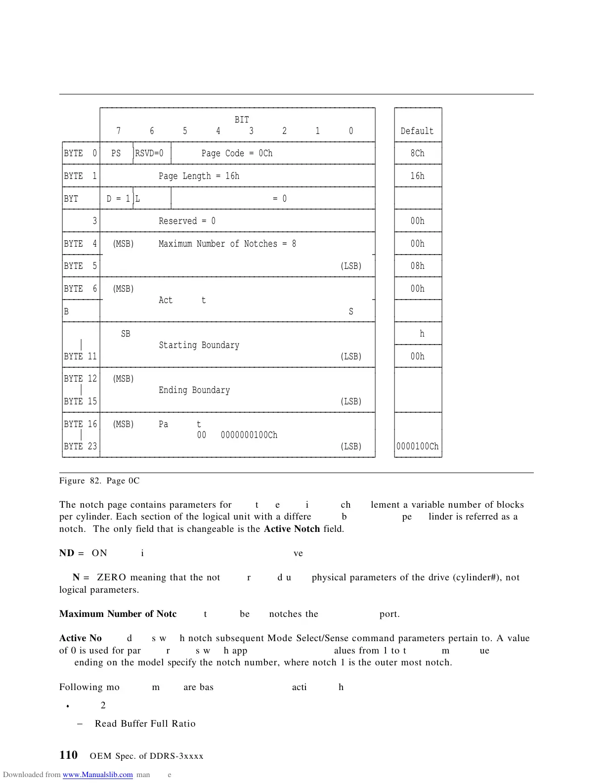
Figure 82. Page 0C
The notch page contains parameters for direct-access devices which implement a variable number of blocks
per cylinder. Each section of the logical unit with a different number of blocks per cylinder is referred as a
notch. The only field that is changeable is the Active Notch field.
ND = ONE meaning that this device is a notched drive.
LPN = ZERO meaning that the notches are based upon physical parameters of the drive (cylinder#), not
logical parameters.
Maximum Number of Notches is the number of notches the drive can support.
Active Notch indicates which notch subsequent Mode Select/Sense command parameters pertain to. A value
of 0 is used for parameter values which apply to all notches. Values from 1 to the maximum value
depending on the model specify the notch number, where notch 1 is the outer most notch.
Following mode parameters are based on the current active notch:
Page 2
− Read Buffer Full Ratio
110 OEM Spec. of DDRS-3xxxx
 Loading...