6.3 LED Circuit
Jumper pin #1 and #2 are used to drive an external LED.
Instead of the the jumper pins, the following pins can be used to drive LED.
68-Pin Model : Auxiliary Connector Pin #8 and #11.
80-Pin Model : SCA-2 Connector Pin #77 as shown in 6.3.3, “80-Pin Model” on page 38.
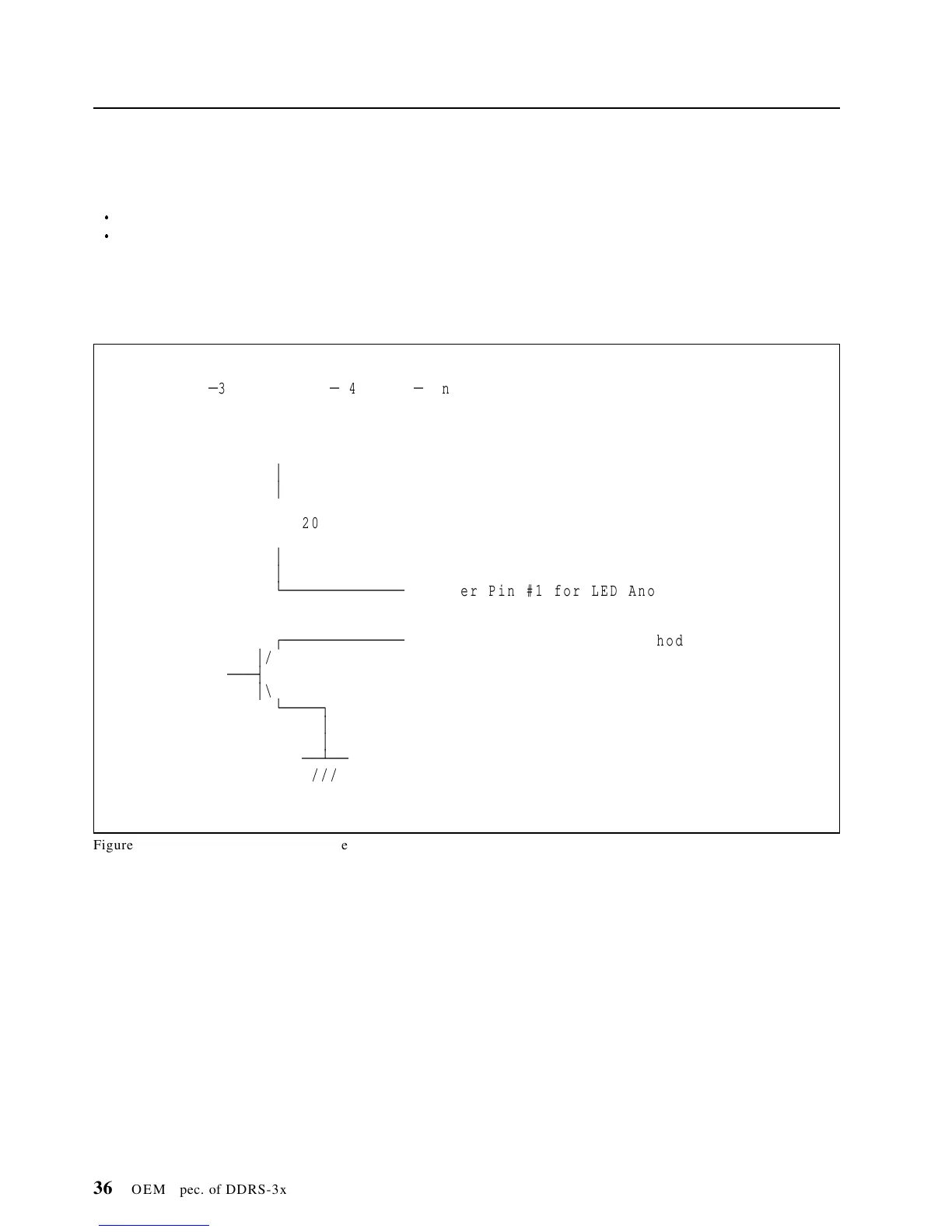
The schematics of LED circuit on each model are as follows.
6.3.1 50-Pin Model
DDRS
Ä
39130 / DDRS
Ä
34560 50
Ä
Pin Model
+5V
o
³
³
>
< 620 Ohm
>
³
³
ÀÄÄÄÄÄÄÄÄÄÄÄÄÄ
o Jumper Pin #1 for LED Anode
ÚÄÄÄÄÄÄÄÄÄÄÄÄÄ
o Jumper Pin #2 for LED Cathod
³
/
ÄÄÄ´
³
\
ÀÄÄÄÄ¿
³
³
ÄÄÁÄÄ
///
Figure 28. LED Circuit of 50-Pin Model
36 OEM Spec. of DDRS-3xxxx

 Loading...