Do you have a question about the IBM DDRS-39130 - Ultrastar 9.1 GB Hard Drive and is the answer not in the manual?
| Storage Capacity | 9.1 GB |
|---|---|
| Interface | SCSI |
| Form Factor | 3.5 inch |
| Rotation Speed | 7200 RPM |
| Cache | 512 KB |
| Data Transfer Rate | 20 MB/s |
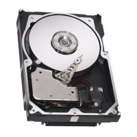
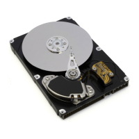
Overview of IBM 3.5 inch SCSI drives and specifications.
Lists ANSI standards and documents related to SCSI-2 and SCSI-3.
Provides warnings regarding handling the drive to prevent damage.
Details the functions of the drive's microprocessor and logic modules.
Describes the HDA assembly, air circulation, and spindle motor.
Presents capacity details for DDRS-39130 and DDRS-34560 drives.
Provides key technical specifications like transfer rates, buffer size, and speed.
Defines command overhead time requirements, excluding seek and latency.
Details mechanical positioning times including seek and settling.
Details the average latency based on spindle rotational speed.
Lists disk-to-buffer and buffer-to-host transfer rates for different interfaces.
Analyzes sequential access performance metrics.
Analyzes random access performance metrics.
Describes how drive status is reported to the host system.
Explains how drive errors are handled and reported by the error recovery procedure.
Details the manufacturing format, including optimal data area usage.
Describes spare sectors and their preparation for defect management.
Details electrical interface specifications including connectors.
Details power connector pin assignments for 50 and 68-pin models.
Lists pin assignments for the 50-pin SCSI interface connector.
Lists pin assignments for the 68-pin LVD SCSI interface connector.
Details pin assignments for the 80-pin LVD SCSI interface connector.
Explains active termination features for SE models and lack thereof for LVD.
Provides input and output logic signal levels for SE interface.
Explains the function of each jumper position for device address and mode control.
Shows schematic for connecting an external LED via jumper pins or connector.
Illustrates the LED circuit for the 68-pin model.
Details the typical current wave form during startup and power supply ripple.
Defines the drive's durability in terms of start/stop cycles under various conditions.
Explains the drive's support for failure prediction thresholds via SCSI-3.
Provides visual outlines of 50, 68, and 80-pin drive models.
Details the physical dimensions and weight of the drive.
Emphasizes the importance of keeping the breather hole clear and unobstructed.
Specifies limits for operating vibration resistance.
Details criteria for shock resistance during drive operation.
Details sound power levels for idle and operating modes according to ISO7779.
Covers compliance with US FCC and EEC directives for EMC.
States compliance with UL 1950 safety standard.
Describes the flammability rating of printed circuit boards and other components.
Explains the meaning of FLAG and LINK bits in SCSI messages.
Lists common abbreviations used in SCSI protocol descriptions.
Describes the INQUIRY command for retrieving target parameters and vital product data.
Specifies the data format for standard INQUIRY data (EVPD=0).
Defines the INQUIRY data format for EVPD=1, Page Code=00.
Describes the LOG SENSE command for retrieving statistical drive data.
Contains counters for write errors reported by the drive.
Provides counters for read errors detected by the drive.
Contains counters for non-medium errors, including seek and hardware failures.
Defines the type of page parameter values to be returned.
Specifies which page or pages to return.
Defines the structure of mode parameter headers.
Describes the structure of mode parameter page descriptors.
Provides guidance on using MODE SELECT after MODE SENSE commands.
Explains the format of data returned by the READ CAPACITY command.
Specifies the format of the defect list header data.
Lists and describes the SCSI messages supported by the drive.
Establishes synchronous data transfer mode and negotiation parameters.
Instructs the initiator to restore saved command, data, and status pointers.
Informs the initiator that the current connection will be broken for a long operation.
Directs the drive to clear the present operation and queued commands.
Indicates that a received message was inappropriate or not implemented.
Indicates completion of a linked command without a flag.
Clears all current commands and resets the drive to its initial state.
Details target-generated internal errors and their handling.
Indicates errors occurring in previous commands that returned good status.
Describes how the drive handles degraded mode conditions.
Details rules for command queuing, including tagged and untagged commands.
Describes the division of the data buffer into smaller buffers for caching.
Explains the read-ahead function for improving sequential data access performance.
Explains target behavior in non-arbitrating systems regarding disconnect permission.
Lists the four sources of resets detected by the target.
Describes the actions taken by the drive following a reset.
Details tests executed during power-on self-test.
Describes tests executed by the Send Diagnostics command.
Describes SCAM protocol operation levels for device ID assignment.
Explains the format of sense data returned by the REQUEST SENSE command.
Provides detailed descriptions of sense keys, error codes, and indicators.