6.6 DC Power Requirements
Connection to the product should be made in isolated secondary circuits (SELV). The following voltage
specification is applied at the power connector of the drive.
No special power on/off sequencing is required.
Notes:
1. 12V +/ - 7% is acceptable during spin up, but the spin up time is not guaranteed.
2. Random Seeks at 51.3% duty cycle.
3. Seek Duty = 47%, W/R Duty = 53%, Idle Duty = 0%.
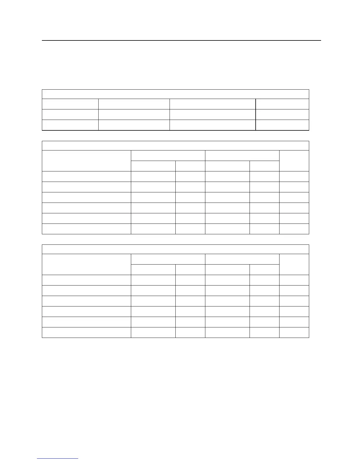
Figure 34. Input Voltage
During run and spin up Absolute max spike voltage Supply rise time
+ 5 Volts Supply 5V+/- 5% 7V 0 - 200 ms
+12 Volts Supply 12V + / - 5% (*1) 15V 0 - 400 ms
Figure 35. Power Supply Current of DDRS-39130 with SCSI Terminator Enabled
(All values in Amps.)
+5Volts +12Volts Total
(W)
Pop Mean Std.Dev Pop Mean Std.Dev
Idle Average 0.32 0.01 0.45 0.01 7.1
Idle ripple (peak-to-peak) 0.21 0.01 0.55 0.03
Seek average (*2) 0.40 0.01 0.95 0.02 13.3
Start up (max) 0.27 0.01 2.00 0.03
Random R/W peak (*3) 0.80 0.02 1.68 0.03
Random R/W average (*3) 0.56 0.01 0.70 0.02 11.2
Figure 36. Power Supply Current of DDRS-34560 with SCSI Terminator Enabled
(All values in Amps.)
+5Volts +12Volts Total
(W)
Pop Mean Std.Dev Pop Mean Std.Dev
Idle Average 0.31 0.01 0.31 0.01 5.30
Idle ripple (peak-to-peak) 0.17 0.01 0.41 0.03
Seek average (*2) 0.40 0.01 0.85 0.02 12.23
Start up (max) 0.27 0.01 2.00 0.03
Random R/W peak (*3) 0.75 0.01 1.55 0.02
Random R/W average (*3) 0.54 0.01 0.60 0.01 9.9
Specification 41
 Loading...