IBM FlashSystem 710 and IBM FlashSystem 810 4
Locations of key components and connectors
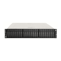
Figure 2 shows the internal components of the FlashSystem unit.
Figure 2. Internal view of the FlashSystem unit
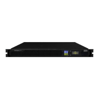
Figure 3 shows the rear of the FlashSystem unit with the Fibre Channel interfaces.
Figure 3. Rear view of the FlashSystem unit with the Fibre Channel interfaces
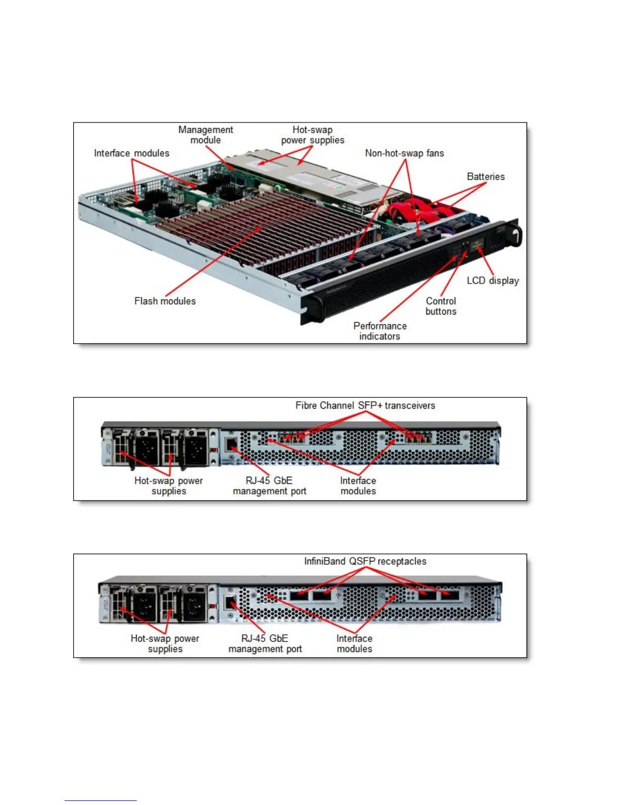
Figure 4 shows the rear of the FlashSystem unit with the InfiniBand interfaces.
Figure 4. Rear view of the FlashSystem unit with the InfiniBand interfaces