IBM 15” Service Manual
34
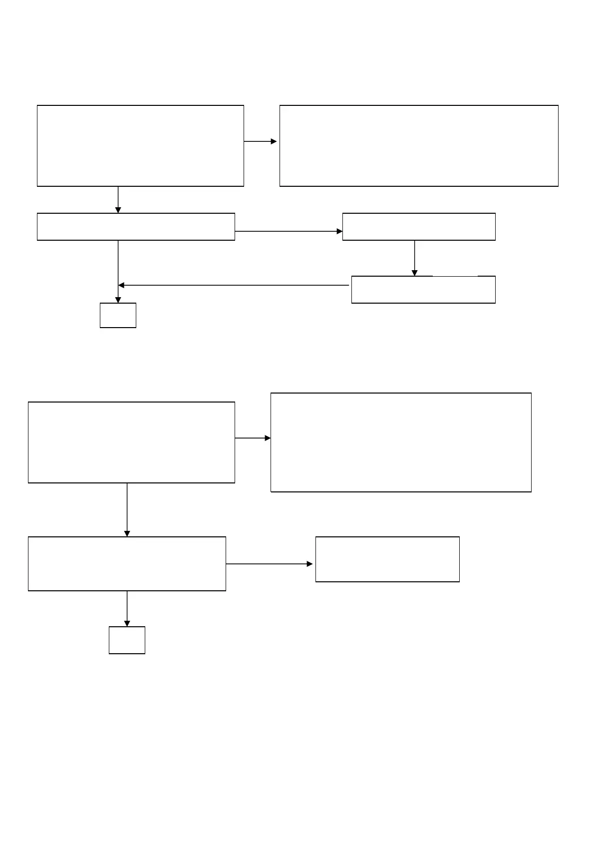
2.PANEL POWER CIRCUIT
3.INVERTER Control Relative Circuit
check R507 should have response
from 0V to 3.3V
When we switch the power switch fro
on to off
NG
Check the PPWR panel power relative circuit, Q501, Q502
In normal operation, when LED =green, R507 should =0 v,
If PPWR no-response when the power switch
Turn on and turn off, replace the U203-GM5120/2120
OK
NG, no Voltage
Measured the Q501 pin 3= 3.3 V?
Check U202 pin 2= 3.3V
OK
OK
Replace Q501 ( AO3401)
Yes
NG
Check the Bklt-On relative circuit, R357, R358,
In normal operation, when LED =green,
R357 Bklt-On should =5 v,
If Bklt-On no-response when the power switch
turn on-off, Replace U203 GM5115/2115
NG, still no screen
OK
NG
Replace Power board
& Re-do white balance
Measured the inverter connector
CN504
pin1 on/off control=3.3V (on)
pin2 PWM signal control dim 0V-5V
Replace power board to new-one
and check the screen is normal?
http://www.wjel.net