Do you have a question about the IBM Aptiva 2124 and is the answer not in the manual?
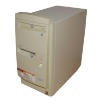
Provides a general overview of the Aptiva Machine Type 2153/2139 and its specifications.
Details the standard and optional features of Aptiva Machine Types 2153/K6, 2153/Celeron, and 2139.
Lists supported peripheral interfaces for adapters, options, and drives in the system unit.
Explains how to use the BIOS Setup Utility to review and change computer and hardware information.
Details the dimensions, weight, environment, power consumption, and electrical input for the system unit.
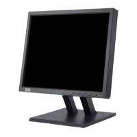
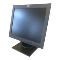
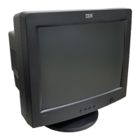
Outlines the power input requirements for the system unit and monitor.
Explains how check procedures diagnose product failures using diagnostic information.
The entry point for all check procedures to determine defective field replaceable units (FRUs).
Lists symptoms, error codes, and beeps to diagnose failures and identify probable causes.
Provides guidance on tracing problems to specific parts or assemblies and measuring voltages.
Guidance for troubleshooting issues when error codes are not present or are intermittent.
Explains diagnostic aids, power-on self test (POST), and diagnostic programs for troubleshooting.
Details the system checks performed by POST each time the system is powered on.
Information on using the PC-Doctor diagnostics program on a diskette for testing components.
Lists the features available in the PC-Doctor diagnostics program, including main menu selections.
Step-by-step instructions for removing and replacing parts of the Machine Type 2153 system unit.
Step-by-step instructions for removing and replacing parts of the Machine Type 2139 system unit.
Instructions to prevent damage to electronic parts from electrostatic discharge (ESD).
Procedure to restore the original system software using the Recovery CD.
Chapter containing system board layouts and jumper settings for locating parts and test points.
Diagram showing the jumper and connector locations on the Machine Type 2153 system board.
Diagram illustrating the jumper and connector locations on the Machine Type 2139 system board.
Details on power supply cable connector pin assignments and voltage checking.
Illustrations showing jumper locations for 3.5-inch hard disk drives for Machine Type 2153.