7. Slide the server into the rack until it snaps into place.
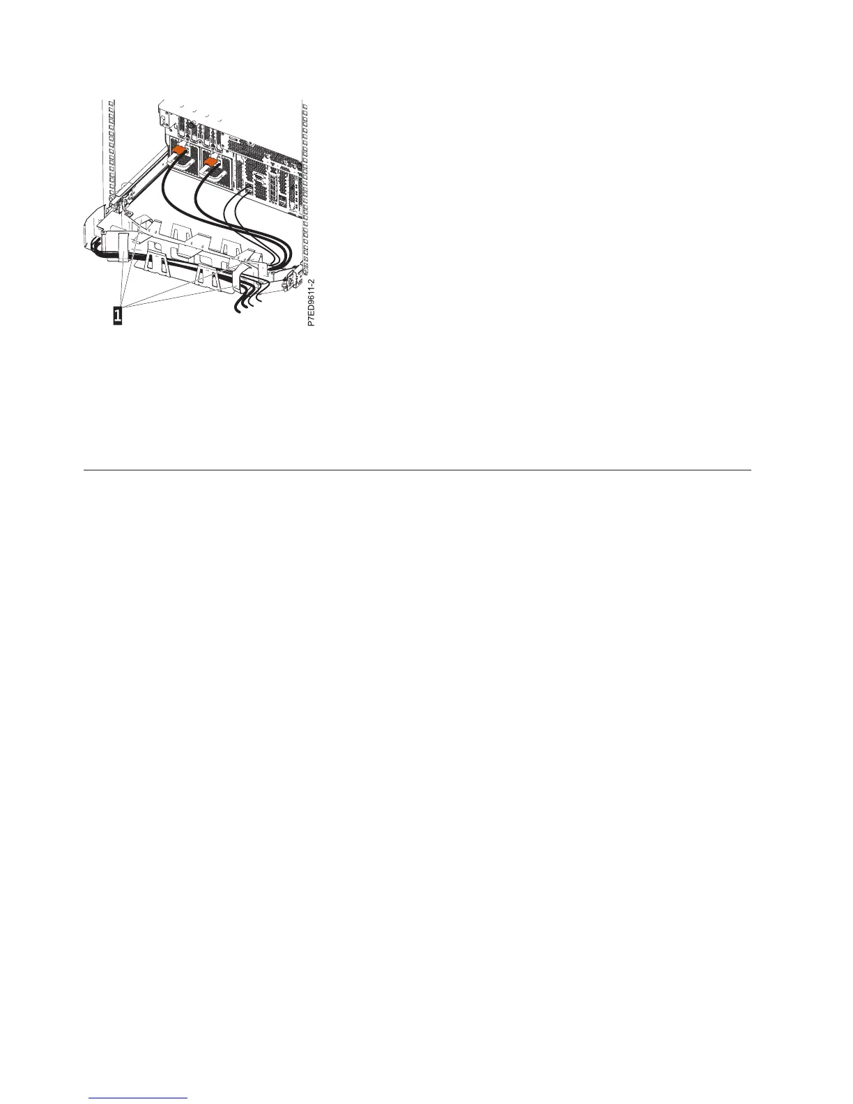
Route the power cords through the cable restraints. For more information about line cord routing and
retention, see Installing VIOS (http://publib.boulder.ibm.com/infocenter/systems/scope/hw/topic/
p7had/p7hadlinecordretention.htm).
Connecting the power cables to the system
You might need to connect power cables to the system. Use this procedure to perform this task.
To connect power cables to the system, follow these steps:
1. Before you connect the power cables to the system, you must remove the power supply shipping
bracket (if present). Ensure that the power supplies have been fully re-seated.
2. While facing the rear of the system unit, route the system power cord through the cable retention
bracket.
Note: You may need to pull the power supply out slightly to route the cable though the retention
bracket. Once you have routed the cable through the retention bracket, re-seat the power supply.
3. Plug the power cord into the power supply.
Note: If the system is equipped with two power supplies, each must have its own power cord
plugged in.
4. Plug the system power cords and the power cords for any other attached devices into the alternating
current (ac) power source. To support redundant power supplies, you must have two separate ac
power sources, one for each system power supply.
Note: The system can take several minutes to apply power. When the power cable is connected, the
green ac LED on the power supply is lit. If it does not light, go to “Common system attention LEDs
and system reference codes” on page 39, follow the instructions, and then return to the next step.
5. If the operator panel displays a blinking green LED, power on the system unit and any devices
connected to the system unit. If the operator panel does not display a blinking green LED, see
“Common system attention LEDs and system reference codes” on page 39.
Figure 15. Power cord attachment and routing
20 Power Systems: Installing the IBM Power 720 Express (8202-E4B) and IBM Power 740 Express (8205-E6B)
 Loading...