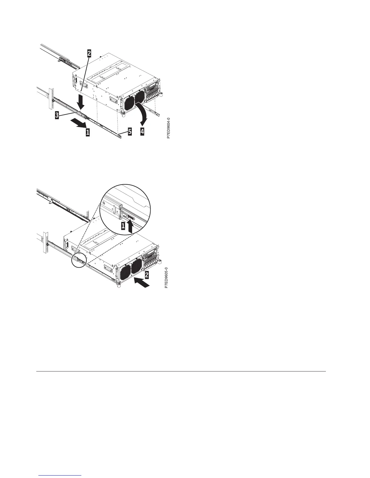
8. Lift the blue release latches (1) in Figure 8 on the slide rails and push the server (2) all the way into
the rack until it clicks into place.
9. Remove the shipping bracket that is on the left side of the rear of the system before you cable it. To
remove the shipping bracket, do the following:
a. Remove the two screws.
b. Pull the bracket off of the system, so that the power supplies unlatch from the bracket.
c. Push the power supplies back into the system, ensuring that they are fully seated and latched.
10. Next, you must install the cable-management arm. For more information, see “Installing the
cable-management arm.”
Installing the cable-management arm
You might need to install the cable-management arm. Use this procedure to perform this task.
To install the cable-management arm, complete the following steps:
Note: The procedure for installing the cable-management arm involves the assembly of the following
parts:
1 Support arm
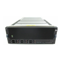
Figure 7. Slide rails extended, server nail heads aligned with slots in rail
Figure 8. Release latches and server
16 Power Systems: Installing the IBM Power 720 Express (8202-E4B) and IBM Power 740 Express (8205-E6B)
 Loading...