5. Fully insert the front drive trays. For instructions, see “Replacing a disk drive in the 7063-CR1
system” on page 5.
6. Using the labels, replace the drive signal cables (A), (B), and drive power cable (C) into the system
backplane as shown in Figure 9 on page 13. Ensure that the cable latch clip snaps into place on the
connector.
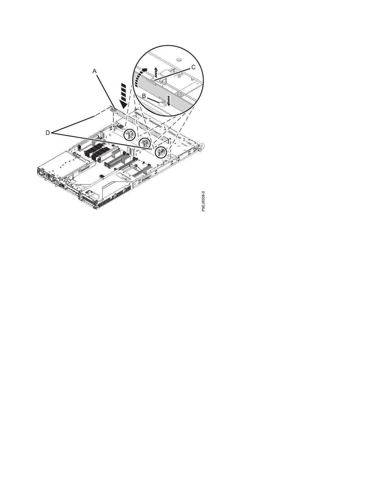
Figure 8. Installing the disk drive backplane
12 Power Systems: Servicing the 7063-CR1 Hardware Management Console system

 Loading...


