13. Place the system backplane on an ESD mat.
Replacing the system backplane in the 7063-CR1
Learn how to replace the system backplane in the IBM 7063-CR1 Hardware Management Console system.
Procedure
1. Ensure that you have the electrostatic discharge (ESD) wrist strap on and that the ESD clip is
plugged into a ground jack or connected to an unpainted metal surface. If not, do so now.
2. Remove the replacement system backplane from the static-protective package and place it on an ESD
mat.
The following steps move the system processor module from the old system backplane to the new system
backplane:
3. Loosen the load arm screw (A) of the system processor heat sink (B) that you are removing with a
#3 Phillips screw driver. The load arm pivots up in the direction that is shown in Figure 34 on page
35.
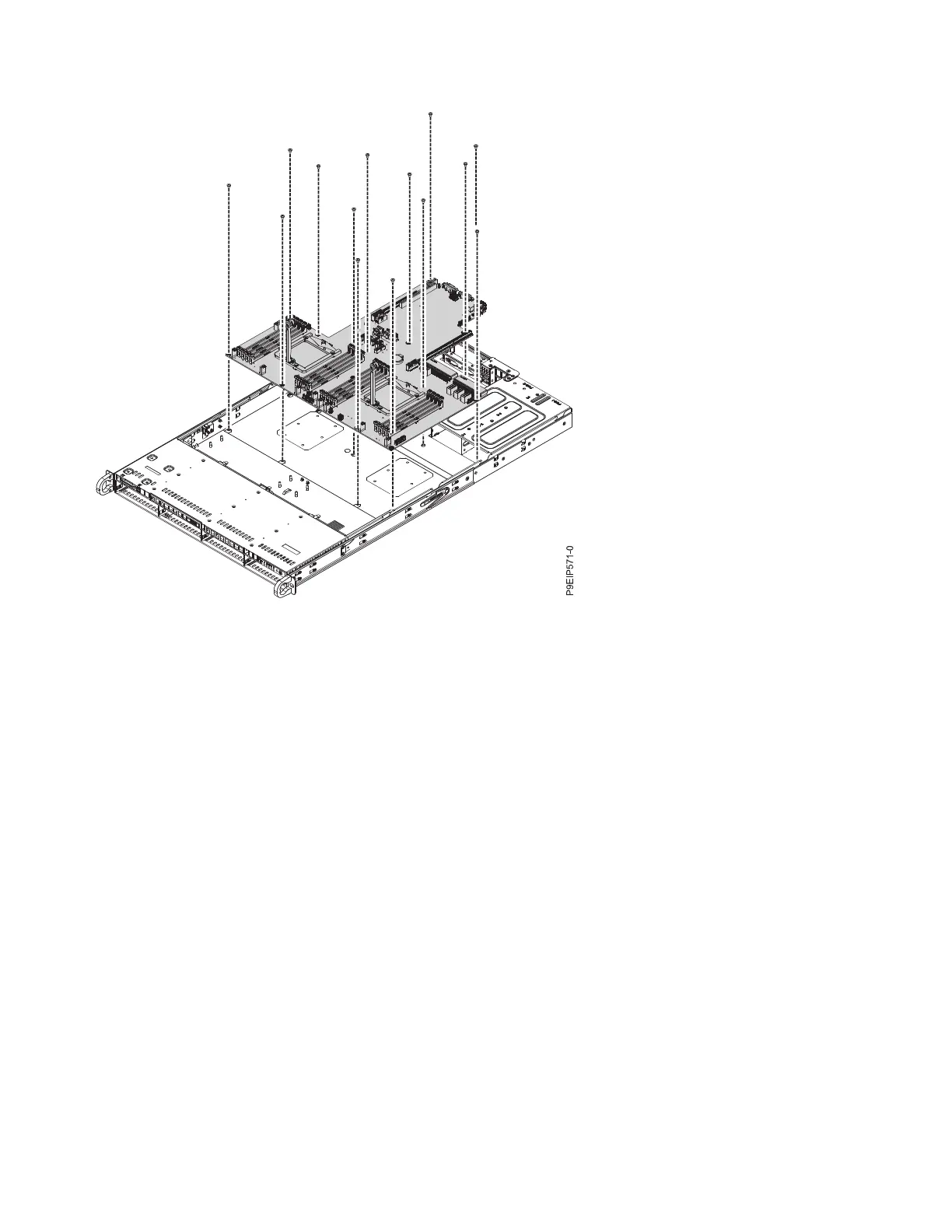
Figure 33. Lifting out the system backplane
34 Power Systems: Servicing the 7063-CR1 Hardware Management Console system

 Loading...


