15. Replace the drive signal and drive power cables in the system backplane. For instructions, see
“Replacing the disk drive backplane in the 7063-CR1” on page 11.
16. Replace the operator panel cable into the system backplane as shown in Figure 42 on page 41.
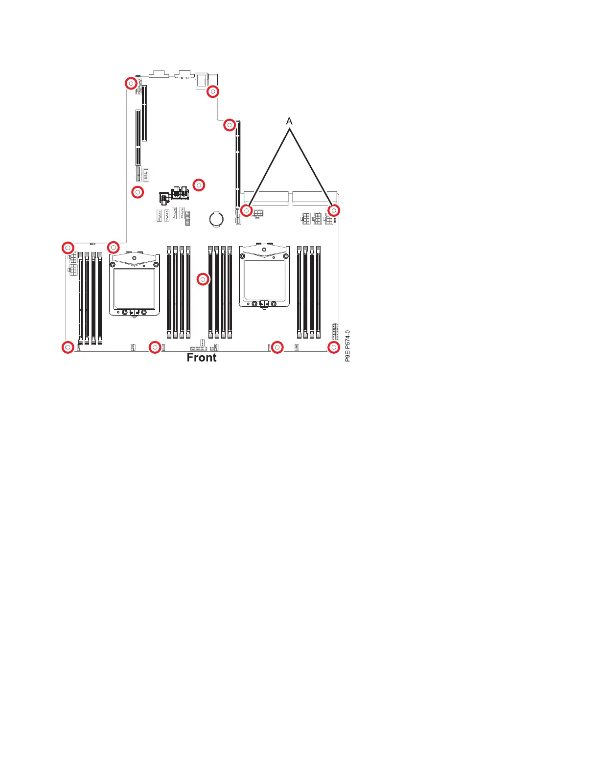
Figure 41. Screw locations. The two screws at (A) are black and slightly longer.
40 Power Systems: Servicing the 7063-CR1 Hardware Management Console system
 Loading...


