3-2 ServeRAID M5014/M5015 SAS/SATA Controller Characteristics
3.1.1 Board Layout and Connector Information
This subsection provides the board layout and connector information for
the controllers. The following subsections provide graphics and
connector information for the controller.
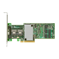
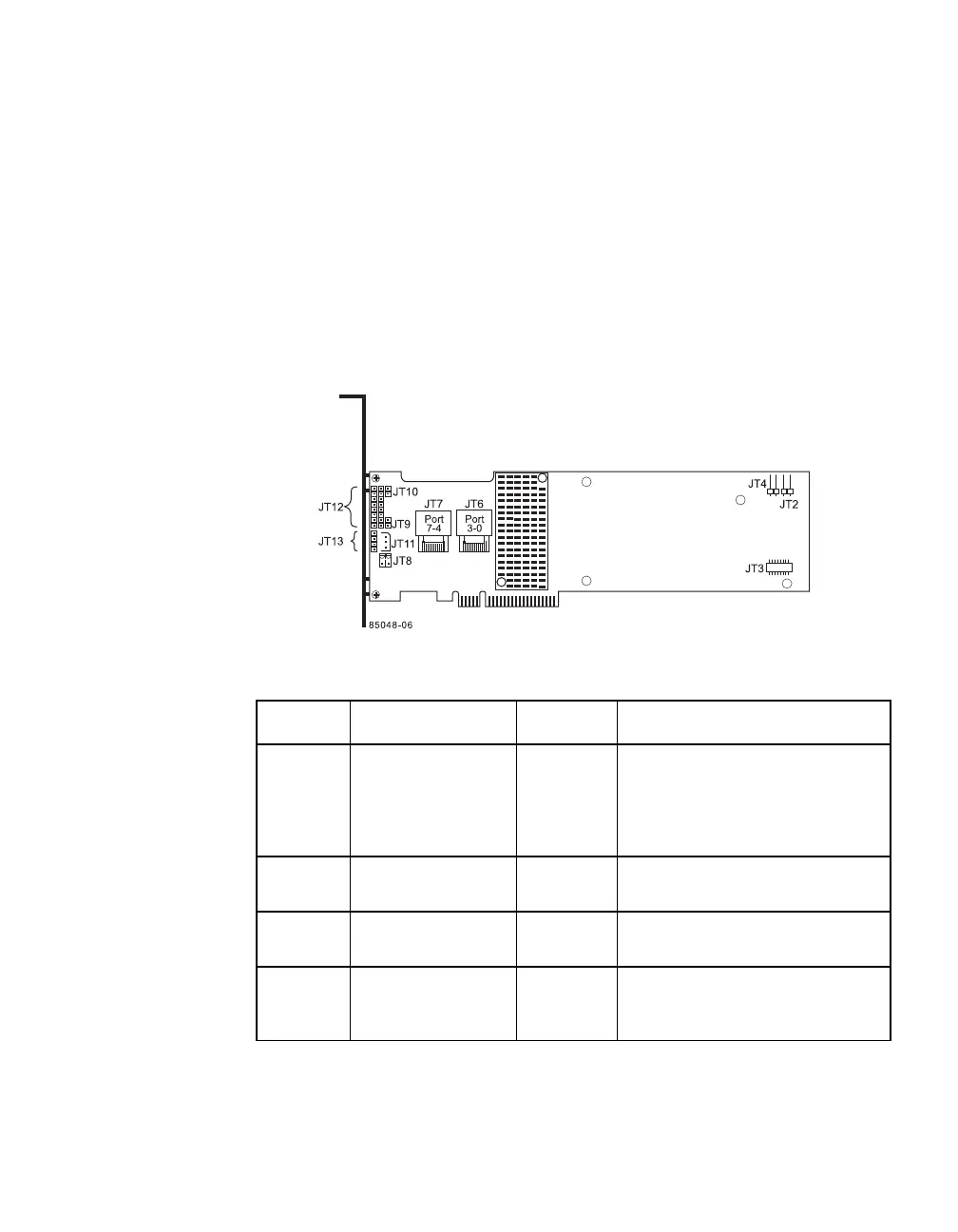
The controller has eight internal SAS/SATA connectors. The following
figure displays the connectors on the controller, while are described on
Tab l e 3 . 1 .
Figure 3.1 Card Layout for the ServeRAID M5014/M5015 RAID
Controllers
Table 3.1 ServeRAID M5014 and ServeRAID M5015 Controllers
Connectors
Connector Description Type Comments
JT1 Write-pending
Indicator (dirty
cache) LED
connector
2-pin
connector
Connects to an LED that indicates
when the data in the cache has yet
to be written to the storage
devices. Used when the write-back
feature is enabled.
JT2 SAS Activity LED
header
2-pin
connector
Connects to an LED that indicates
drive activity.
JT3 Battery Backup Unit
(BBU) connector
20-pin
connector
Connects the BBU unit directly to
the controller.
JT4 Global Drive Fault
LED header
2-pin
connector
Connects to an LED that indicates
whether a drive is in a fault
condition.