Identify the hardware components
The following graphics and descriptions identify the various hardware components
and port locations for the control enclosure.
Control enclosure components
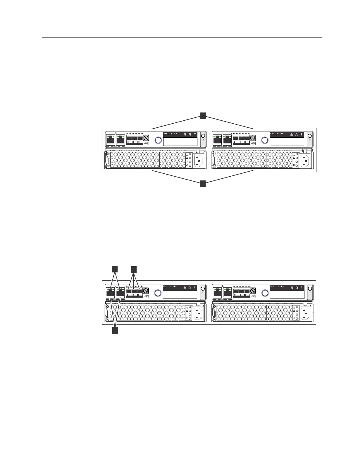
Figure 1 shows the rear view of a control enclosure and identifies the location of
the power supply units and node canisters.
Note: Figure 1 shows the node canisters in their initial configuration, with no host
interface adapter options installed.
Data ports
Figure 2 shows the rear view of a Storwize V3500 control enclosure and identifies
the location of the ports.
v ▌1▐ USB ports. Each canister has two USB ports. One port is used during
installation.
v ▌2▐ Ethernet ports. Each canister has two 1 Gbps Ethernet ports.
Port 1 Must be connected for system management. Can optionally be used for
iSCSI host connectivity.
Port 2 Optional. Can be used for iSCSI host connectivity or to provide an
alternative (redundant) management address.
v ▌3▐ Serial-attached SCSI (SAS) ports. Each canister has three SAS ports. These
ports are used to connect to host systems.
v3500123
OK
IN
1
2
1 2
1 2 3
OK
IN
1
2
1 2
1 2 3
1
2
Figure 1. Rear view of a Storwize V3500 control enclosure
v3500122
OK
IN
1
2
1 2
1 2 3
OK
IN
1
2
1 2
1 2 3
2
1
3
Figure 2. Data ports in the rear of the Storwize V3500 control enclosure
Chapter 1. Before you begin the installation 5
 Loading...


