4. Working from the front of the rack cabinet, remove the clamping screw from
the rail assembly on both sides of the rack cabinet.
5. From one side of the rack cabinet, grip the rail and slide the rail pieces
together to shorten the rail.
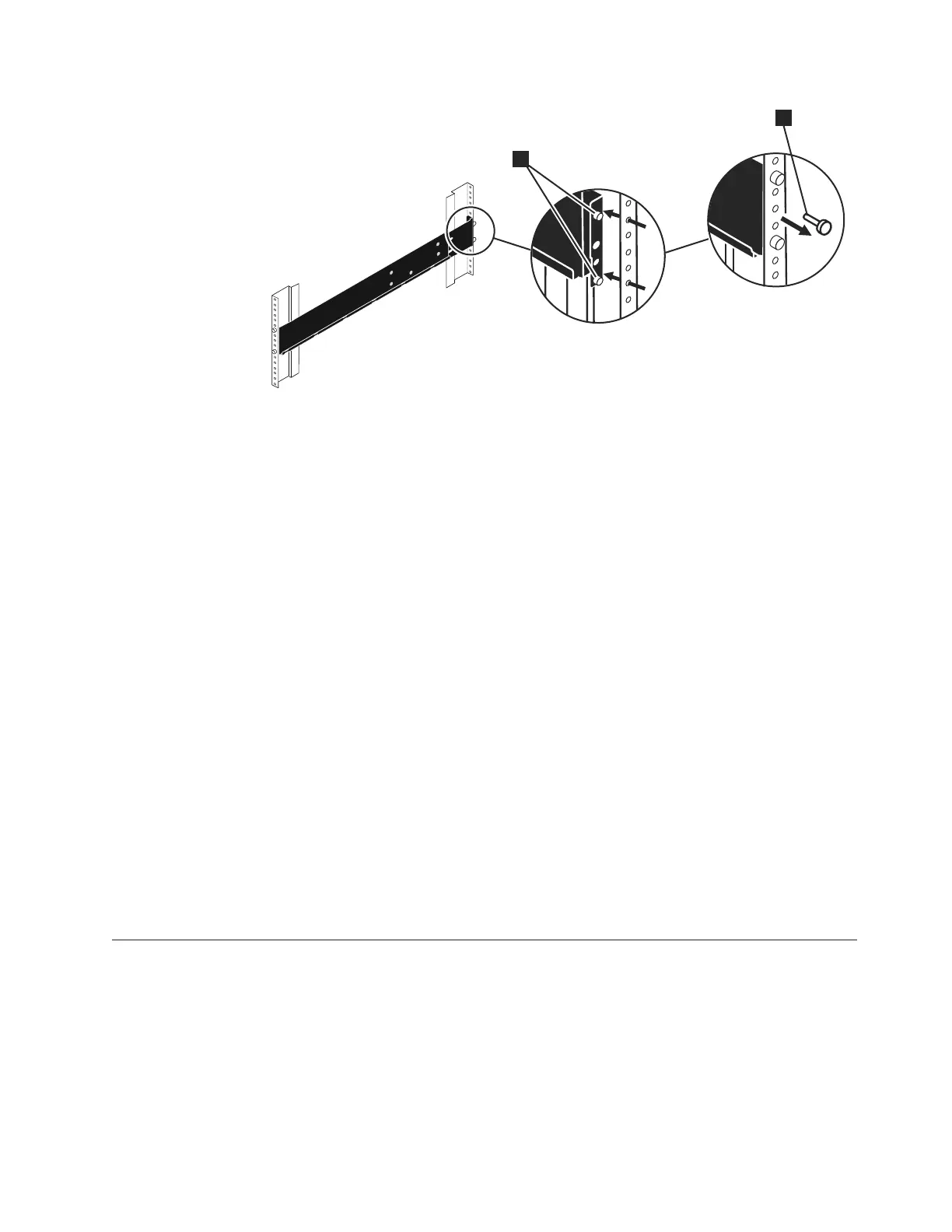
6. Disengage the rail location pins 2.
7. From the other side the rack cabinet, grip the rail and slide the rail pieces
together to shorten the rail.
8. Disengage the rail location pins 2.
9. Starting from the location of the previous rail assembly, align the bottom of
the rail with the bottom of the two rack units. Insert the rail location pins
through the holes in the rack cabinet.
10. Insert a clamping screw into the upper mounting hole between the rail
location pins.
11. Tighten the screw to secure the rail to the rack.
12. Working from the rear of the rack cabinet, extend the rail that you secured to
the front to align the bottom of the rail with the bottom of the two rack units.
Note: Ensure that the rail is level between the front and the back.
13. Insert the rail location pins through the holes in the rack cabinet.
14. Insert a clamping screw into the upper mounting hole between the rail
location pins.
15. Tighten the screw to secure the rail to the rack from the back side.
16. Repeat the steps to secure the opposite rail to the rack cabinet.
Storwize V7000 replaceable units
TheStorwize V7000 consists of several replaceable units. Generic replaceable units
are cables, SFP transceivers, canisters, power supply units, battery assemblies, and
enclosure chassis.
Table 24 on page 118 provides a brief description of each replaceable unit.
1
2
svc00650
Figure 39. Removing a rail assembly from a rack cabinet
Chapter 8. Replacing parts 117

 Loading...


