11. Connect one end of the applicable signal cable into the rear of the drive and
make sure that the other end of this cable is connected into the applicable
connector on the system board.
12. Route the signal cable so that it does not block the airflow to the rear of the
drives or over the microprocessor and dual inline memory modules (DIMMs).
13. Connect the power cable to the rear of the drive. The connectors are keyed
and can be inserted only one way.
14. Install the upper bezel (see “Installing the upper bezel” on page 175).
15. Install the lower bezel (see “Installing the lower bezel” on page 173).
16. Install and lock the side cover (see “Installing the side cover” on page 167).
17. Reconnect the external cables and power cords; then, turn on the attached
devices and turn on the server.
Removing a simple-swap hard disk drive
This procedure applies only to 4U server models with non-hot-swap power supplies.
Attention: Simple-swap hard disk drives are not hot-swappable. Disconnect all
power from the server before you remove or install a simple-swap hard disk drive.
To remove a simple-swap SATA hard disk drive on 4U server models that have
non-hot-swap power supplies, complete the following steps.
1. Read the safety information that begins on page vii and “Installation guidelines”
on page 163.
2. Turn off the server and all attached devices; then, disconnect all power cords
and external cables.
3. Remove the bezel (see “Removing the bezel” on page 169).
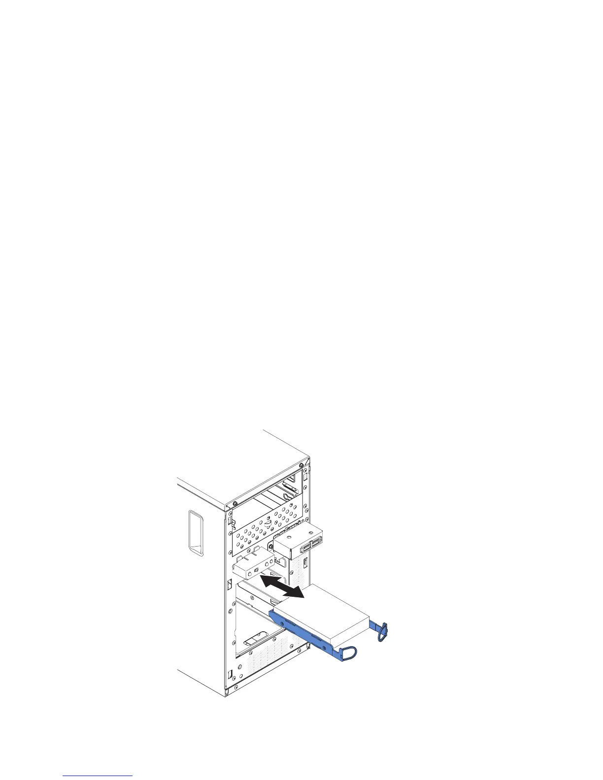
4. Pull the round blue loops of the drive assembly that is to be removed toward
each other; then, pull the assembly out of the bay.
194 IBM System x3100 M4 Type 2582: Problem Determination and Service Guide

 Loading...


