Attention: Do not touch the thermal material on the bottom of the heat sink.
Touching the thermal material will contaminate it. If the thermal material on the
microprocessor or heat sink becomes contaminated, contact your service
technician.
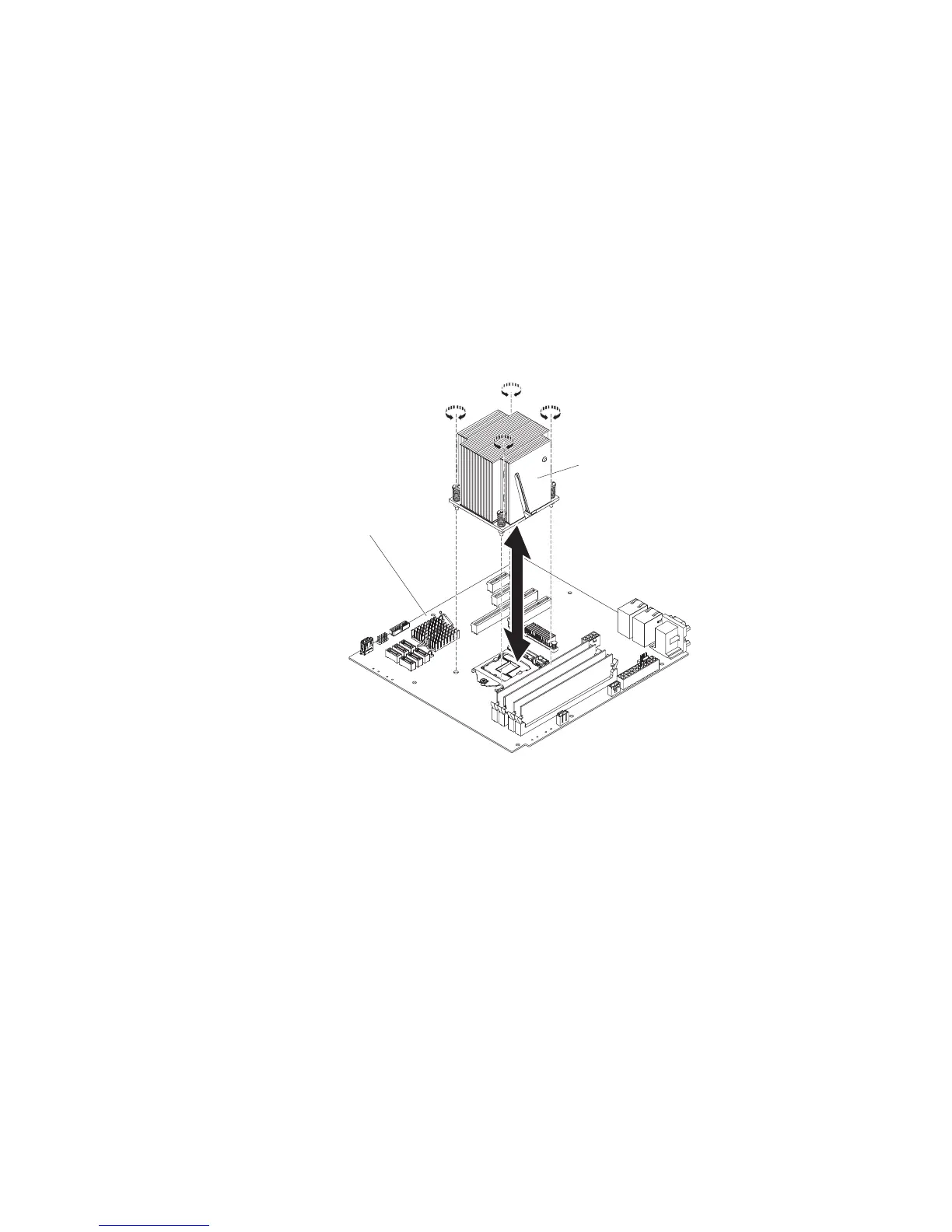
a. Align the screw holes on the heat sink with the holes on the system board.
b. Tighten the screws with a screwdriver, alternating among the screws until
they are tight. If possible, each screw should be rotated two full rotations at
a time. Repeat until the screws are tight. Do not overtighten the screws by
using excessive force.
Important: Do not touch the thermal material on the bottom of the heat
sink. Touching the thermal material will contaminate it. If the thermal
material on the microprocessor or heat sink becomes contaminated,
contact your service technician.
Heat sink
System board
7. Reconnect any cables that you disconnected during the removal of the old
microprocessor.
8. Secure the SATA signal cables with the retention-clips.
9. Install the air duct.
10. Install the side cover (see “Installing the side cover” on page 167).
11. Stand the server back up in its vertical position.
12. Install bezel (see “Installing the bezel” on page 171).
13. Reconnect the external cables and power cords; then, turn on the attached
devices and turn on the server.
To install the microprocessor and heat sink on the 5U server model with hot-swap
power supplies (Model name: 2582-F4x), complete the following steps. For 4U
server models with non-hot-swap power supplies, please see the above
sub-section.
1. Touch the static-protective package that contains the microprocessor to any
unpainted metal surface on the server. Then, remove the microprocessor from
the package.
Chapter 5. Removing and replacing server components 255

 Loading...


