v Follow the suggested actions in the order in which they are listed in the Action column until the problem
is solved.
v See Chapter 4, “Parts listing, System x3100 M4 Type 2582,” on page 151 to determine which components
are customer replaceable units (CRU) and which components are field replaceable units (FRU).
v If an action step is preceded by “(Trained service technician only),” that step must be performed only by a
trained service technician.
v Go to the IBM support website at http://www.ibm.com/supportportal/ to check for technical information,
hints, tips, and new device drivers or to submit a request for information.
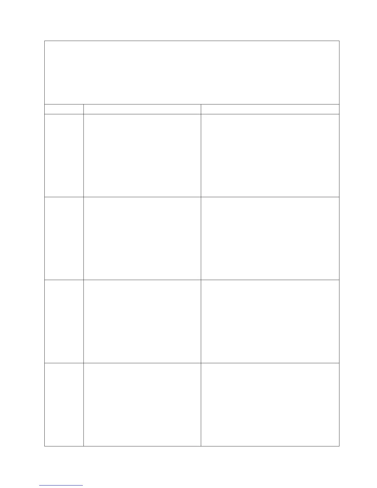
Error code Description Action
001800B Microprocessors with mismatched cache size.
1. Make sure that the microprocessor is on the
ServerProven website at http://www.ibm.com/
servers/eserver/serverproven/compat/us/.
2. Check the IBM support website for a firmware
update and update the server firmware to the
latest level (see “Updating the firmware” on page
267).
3. (Trained service technician only) Remove and
replace the affected microprocessor (error LED is
lit) with a supported type (see “Installing a
microprocessor and heat sink” on page 254).
001800C Microprocessors with mismatched cache
type.
1. Make sure that the microprocessor is on the
ServerProven website at http://www.ibm.com/
servers/eserver/serverproven/compat/us/.
2. Check the IBM support website for a firmware
update and update the server firmware to the
latest level (see “Updating the firmware” on page
267).
3. (Trained service technician only) Remove and
replace the affected microprocessor (error LED is
lit) with a supported type (see “Installing a
microprocessor and heat sink” on page 254).
001800D Microprocessors with mismatched cache
associativity.
1. Make sure that the microprocessor is on the
ServerProven website at http://www.ibm.com/
servers/eserver/serverproven/compat/us/.
2. Check the IBM support website for a firmware
update and update the server firmware to the
latest level (see “Updating the firmware” on page
267).
3. (Trained service technician only) Remove and
replace the affected microprocessor (error LED is
lit) with a supported type (see “Installing a
microprocessor and heat sink” on page 254).
001800E Microprocessors with mismatched model.
1. Make sure that the microprocessor is on the
ServerProven website at http://www.ibm.com/
servers/eserver/serverproven/compat/us/.
2. Check the IBM support website for a firmware
update and update the server firmware to the
latest level (see “Updating the firmware” on page
267).
3. (Trained service technician only) Remove and
replace the affected microprocessor (error LED is
lit) with a supported type (see “Installing a
microprocessor and heat sink” on page 254).
Chapter 3. Diagnostics 29
 Loading...


