s. 24 / 40
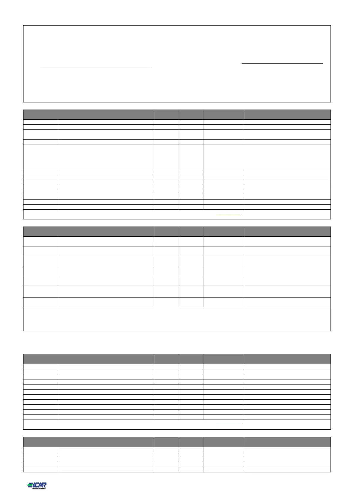
P17.02 - Defines which sensor is providing the measure of the temperature inside the panel:
Internal sensor - Sensor built into the controller.
AINx - Temperature of PT100 expansion module with analog inputs.
NTCx - Temperature by NTC expansion module protection harmonics.
P17.03 – Channel number (x), relative to the previous parameter.
P17.04 - P17.05 - Start and stop temperature for the cooling fan of the panel, expressed in the unit set by P17.01.
P17.06 - Threshold for generation of alarm A07 Panel temperature too high .
P17.07 - Enables the measurement of the capacitor current overload, calculated from the waveform of the applied voltage. Note: You can use this protection only if the capacitors
are not equipped with filtering devices such as inductors or similar.
P17.08 – Trip threshold for the capacitors overload protection (alarm A08), that will arise after a integral delay time, inversely proportional to the value of the overload.
P17.09 - Threshold beyond which the integral delay for tripping of the overload alarm is zeroed, causing the immediate intervention of the A08 alarm.
P17.10 - Delay time for the resetting of overload alarm.
P17.11 - Enables the measurement of the actual power of the step, performed each time they are switched in. The measure is calculated, as the current measurement is referred to the
whole load of the plant. The measured power of the steps is adjusted (trimmed) after each switching and is displayed on the step life statistic page.
P17.13 - Maximum voltage alarm threshold, referred to the rated voltage set with P02.21, beyond which the alarm A06 Voltage too high is generated.
P17.14 - Undervoltage alarm threshold, referred to the rated voltage set with P02.21, below which the alarm A05 voltage too low is generated.
M18 – HARMONIC PROTECTION
Temperature alarm threshold 1
Temperature alarm threshold 2
For more information download the complete manual of the RPC 8BGA power factor controller from the web site www.icar.com download area concerning the low voltage power
factor correction systems.
Step disconnection passing in MAN mode
Count maintenance interval 1
Count maintenance interval 2
Count maintenance interval 3
P19.01 - If set to ON, when switching from AUT mode to MAN mode, steps are disconnected in sequence.
P19.02- Time interval after which it is necessary to perform maintenance.
P19.03– If set to "Always" will count the time in which the controller 8BGA stay lit when set to "Step inserted " count the time in which a pleasant step is inserted.
P19.04-P19.06 – See P19.02
P19.05-P19.07 – See P19.03
(*) If the controller is installed on the ICAR cabinet
M20 – LIMIT THRESHOLDS (LIMn,n=1…16)
For more information download the complete manual of the RPC 8BGA power factor controller from the web site www.icar.com download area concerning the low voltage power
factor correction systems.
M21 – COUNTERS (CNTn,n=1…8)
OFF-ON-INPx-OUTx-LIMx-REMx
Description of the counter
 Loading...