English
10
SERVICE MODULARI06/2014
4.5 CONTROL SEQUENCE
• At the start of the freezing cycle, the contacts of the mag
netic switch mechanically operated by the actuator plate of
the deflector cover are closed, thereby via electronic control
board closing the circuit to the main contactor coil and con
sequently to the compressor and fan motors and 30" later,
to the water pump motors.
• Then, as the ice thickness reaches the value that corresponds
to the full cube size, the film of water that constantly cas
cades over the slab of ice formed on the evaporator, arrives
to establish a contact between the two fingers energised at
low voltage of the ice sensor control, located on the front
upper right side of the evaporator. If the contact between
the two fingers of the ice sensor remains established by the
film of water for more than 10 seconds, a small relay of the
electronic board, get energized, controlling simultaneously
the hot gas valve, the water drain valve and the harvest assist
solenoid.
Note: in case of failure of ice level sensor, the P.C. Board turns - on
automatically the unit into the defrost cycle when the freezing
cycle reaches 30 or 40 minutes according to the operation of the
fan motor during the freezing cycle.
• At this point, the unit initiates the defrost cycle.
• The hot gas circulating into the evaporator serpentine causes
a slight melting of ice cubes which get released from their
molds. In the mean time the harvest assist solenoid is also
energized pushing out the ice plate.
• Once entirely released the ice cubes drop simultaneously
into the ice storage bin below; by doing so they move apart
from the evaporator bottom end the plastic deflector.
• This plastic deflector has on its side a magnetic switch that
on account of the deflector swinging motion, caused by the
ice while dropping in the bin, opens and closes their con
tacts.
• This will, in turn, disactivate the relay contacts that controls
the hot gas, harvest assist solenoid and water drain valve
which get deenergized allowing the unit to start a new freez
ing cycle.
• When the ice bin is full of ice, the last batch of ice cubes re
leased from the evaporator accumulates to keep the bottom
end of the plastic deflector in open position; with the mag
netic switch contacts open for longer than 30'’ the entire unit
stops with the glowing of the corresponding LED.
• The machine will restart when the ice deflector will be back
in its normal vertical position provided that 3' are elapsed
from unit stop. If not the machine will delay its restart till 3'
are elapsed with the blinking of the green LED.
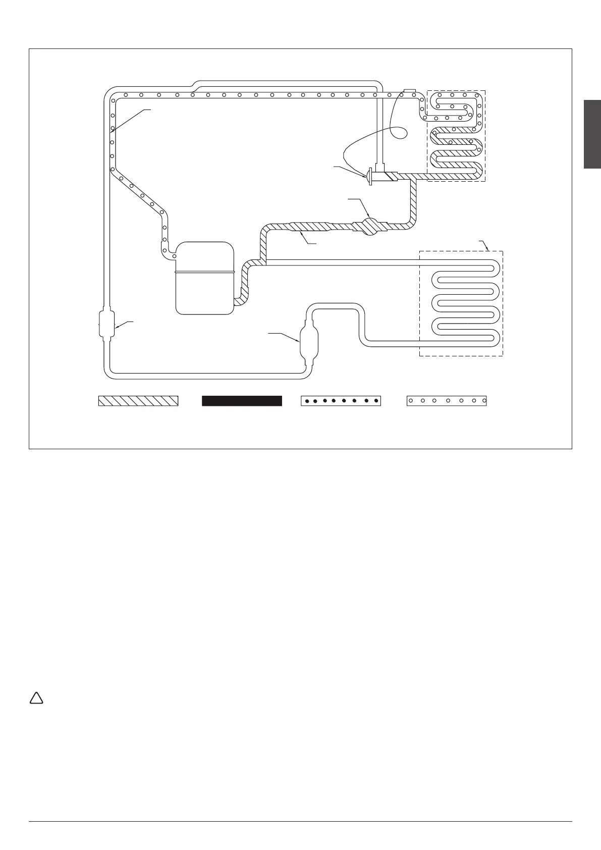
H
EA T
E
XC HAN GE R
E
VA POR ATOR
CO NDE NSE R
C
OM PRE SSOR
E
XP ANS IO N V ALVE
HO T G AS SO LENOID V ALVE
AI R O R WAT ER
DR IER
ST RAI NE R
R
EC EIV ER
(W ATE R COOLE D O NL Y)
LO W P RE SSU RE VA PO RLO W P RE SSU RE LIQUI DHI GH PR ESS UR E L IQUIDHI GH PR ESS UR E V APOR
HARVEST (DEFROST) CYCLE
REFRIGERATION SYSTEM SCHEMATIC