English
13
SERVICE MODULARI 06/2014
6. COMPONENT DESCRIPTION
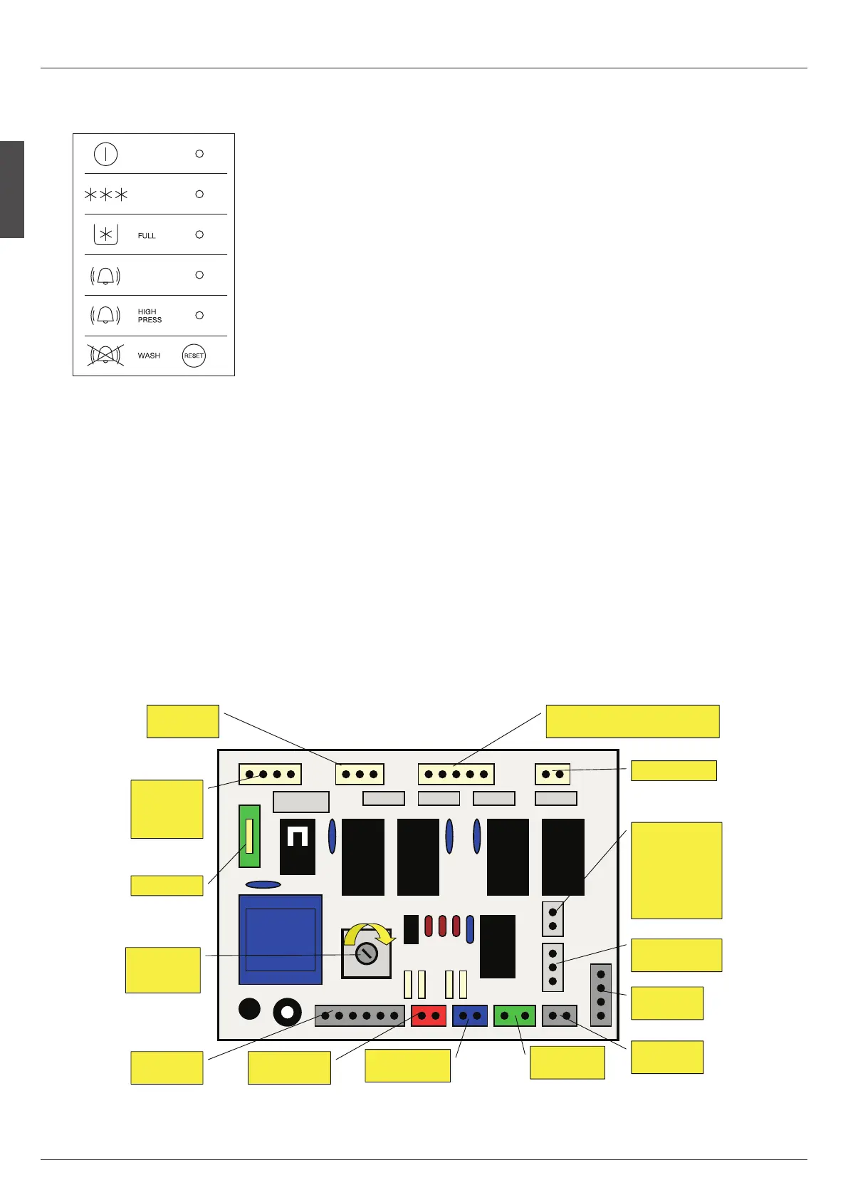
6.1 FRONT CONSOLE PANEL
Equipped with five LED plus a push button that when glow
or blink are monitoring:
LED Nr. 1
Electrical power supply.
LED Nr. 2
Operation.
LED Nr. 3
Bin full./Washing.
LED Nr. 4
Alarm.
LED Nr. 5
Alarm high pressure.
BUTTON B
Reset/Washing.
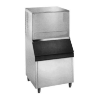
6.2 P.C. BOARD
• Located in the control box, this board is the brain of the sys
t
em as it governs the ice machine cyclematic through sen
sors, relays and switch. It consists of two separated printed
circuits one at high and the other at low voltage integrated
with a fuse, of four connectors for the sensors/switches con
denser sensor BLACK , magnetic switch GREEN ice thick
n
ess sensor RED water level sensor BLUE, of two jumpers
one J1 for factory use only and the second J2 for the se
lection between one water fill up or continuous water fill up,
of one outlet connector front LED display black one serial
port connector black and of four plug in terminals for input
and output power.
• With J2 closed the P.C. Board is set up for water fill up at be
ginning freeze mode. When J2 is open the PC Board is set up
for continuous water filling mode.
The P.C. Board is equipped by an electronic safety timer that
turnson automatically the unit to defrost cycle when freez
ing cycle is longer then 30 or 40 minutes and tripsoff com
pletely unit when defrost cycle is longer then 3,5 minutes
4th Red LED ON.
A trimmer, located close to the transformer, can change the
current received back from the Ice Tickness Sensor according
to the Electrical Conductivity of the water.
6.3 COMPRESSOR CONTACTOR
• Located in the control box, the compressor contactor func
tions to carry the compressor line current. The contactor is
wired to receive power from the P.C. Board.
Alimentazione
Electrical Power Supply
Funzionamento
Operation
Deposito Pieno/Lavaggio
Storage Full/Washing
Allarme
Alarm
Allarme Alta Pressione
High Pressure Alarm
Reset/Lavaggio
Reset/Washing
q
w
e
r
t
ò
B
2J
1J
RESNEDNOC
RESNEDNOC
ROSNES
ROSNES
CITENGAM
CITENGAM
HCTIWS
HCTIWS
SSENKCIHTECI
SSENKCIHTECI
ROSNES
ROSNES
YALPSID
YALPSID
ROTCENNOC
ROTCENNOC
ESUF
ESUF
NIREWOP
NIREWOP
YTEFASDNA
YTEFASDNA
ERUSSERP
ERUSSERP
SLORTNOC
SLORTNOC
NAF
NAF
SROTOM
SROTOM
PMUPRETAW
PMUPRETAW
RETAW,SAGTOH,ROSSERPMOC
RETAW,SAGTOH,ROSSERPMOC
SEVLAVNIARDDNATELNI
SEVLAVNIARDDNATELNI
RETAW
RETAW
YTIVITISNES
YTIVITISNES
TNEMTSUJDA
TNEMTSUJDA
TUOPMUJ-.O.N
TUOPMUJ-.O.N
SUOUNITNOC
SUOUNITNOC
GNILLIFRETAW
GNILLIFRETAW
NIPMUJ-.C.N
NIPMUJ-.C.N
PULLIFRETAW
PULLIFRETAW
GNINNIGEB
GNINNIGEB
YLNOEZEERF
YLNOEZEERF
-
-
+
+
LEVELRETAW
LEVELRETAW
ROSNES
ROSNES
LAIRES
LAIRES
ROTCENNOC
ROTCENNOC
YROTCAFROF
YROTCAFROF
YLNOESU
YLNOESU
PC BOARD