Caution
ELECTRICAL SHOCK HAZARD
– Turn off power at the main service panel by removing
the fuse or switching the appropriate circuit breaker to the OFF position before
removing the existing thermostat.
IMPORTANT: Thermostat installation must conform to local and national building and electrical
codes and ordinances.
Important Safety Information
WARNING!
:
Always turn off power at the main power supply before installing, cleaning,
or removing thermostat.
• Thisthermostatisfor24VACapplicationsonly;donotuseonvoltagesover30VAC
• Donotshortacrossterminalsofgasvalveorsystemcontroltotestoperation;thiswilldamageyour
thermostatandvoidyourwarranty
• Allwiringmustconformtolocalandnationalelectricalandbuildingcodes
• Usethisthermostatonlyasdescribedinthismanual
General Description
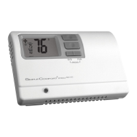
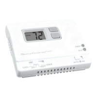
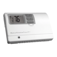
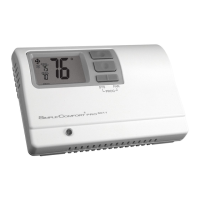
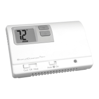
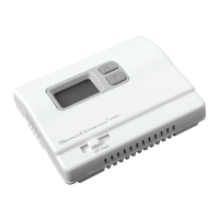
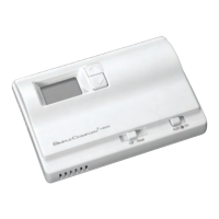
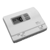
TheSimpleComfort
®
FS1500L/FS1500VLthermostatisadigital,mercury-free,non-programmable,
electronicthermostat.
•Compatiblewithsingle-stageheatingsystems
•Compatibleasamasterthermostatinzonedsystemapplications
•System Customization:Choosethreeavailabletemperaturedifferentialsettings
To Remove Existing Thermostat
1.Turnoffpowertotheheatingsystembyremovingthefuseorswitchingofftheappropriatecircuit
breaker.
2.Removecoverofoldthermostat.Thisshouldexposethewires.
3.Labeltheexistingwireswiththeenclosedwirelabelsbeforeremovingwires.
4.Afterlabelingwires,removewiresfromwireterminals.
5.Removeexistingthermostatbasefromwall.
6.Refertothefollowingsectionsforinstructionsonhowtoinstallthisthermostat.
Replacing Wiring Labels
Replacetheoldlabelswiththe
enclosednewlabels.
Old New Type
F,G G Fancontrolrelay
H,W,4 W Heatingcontrol
M,4,RH,RS,R R Transformer,hotside
N/A S1,S2 Optionalremotesensor
Specifications
Electrical rating: •Millivoltto30VAC/VDC
•DCPower:3.0VDC(2“AA”alkalinebatteriesincluded)
•1ampmaximumperterminal,2ampmaximumtotalload
Temperature control range: 35°Fto75°FAccuracy:±1°F
Back Light:Notavailableonsomemodels
Differential Rage:1°Fto3°F
System congurations:1-stageheat,gas,oil,electric
Terminations:R,W,G,S1,S2
Installation, Operation & Application Guide
For more information on our complete range of American-made
products – plus wiring diagrams, troubleshooting tips and more,
visit us at www.icmcontrols.com
Manual Changeover
Non-Programmable
Battery
• Controls Single Stage Heating Systems
• Millivolt and Hydronic (water or steam) System Compatible
• Compatible with Gas and Electric Systems
• Backlit Display
• Mercury-Free,
Environmentally Safe
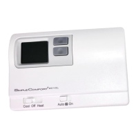
FS1500L/FS1500VL
GARAGE THERMOSTAT
Non-Programmable Electronic Thermostat
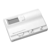
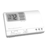
Parts Diagram (Horizontal model shown)
Battery
Compartment
Electric/GasJumper
HighTemperatureSwitch
ModeSwitch
FanSwitch
Thermistor
Note: Mount thermostat about ve feet above the oor. Do not mount the thermostat on an outside
wall, in direct sunlight, behind a door, or in an area affected by a vent or duct.
1. Turnoffpowertotheheatingsystembyremovingthefuseorswitchingofftheappropriatecircuit
breaker.
2. MovetheFan Auto/OnswitchintoAuto position.
3. Toremovecover,insertandtwistacoinorscrewdriverintheslotsonthesidesofthethermostat.
4. Putthermostatbaseagainstthewallwhereyouplantomountit(Besurewireswillfeedthrough
thewireopeninginthebaseofthethermostat).
5. Marktheplacementofthemountingholes.
6. Setthermostatbaseandcoverawayfromworkingarea.
7. Usinga3/16”drillbit,drillholesintheplacesyouhavemarkedformounting.
8. Useahammertotapsuppliedanchorsinmountingholes.
9. Alignthermostatbasewithmountingholesandfeedthecontrolwiresthroughwireopening.
10.Usesuppliedscrewstomountthermostatbasetowall.
11. Insertstripped,labeledwiresinmatchingwireterminals.See“WiringDiagrams”sectionofthis
manual.
CAUTION!
: Be sure exposed portion of wires does not touch other wires.
12.Tightenscrewsonterminalblock.Gentlytugwiretobesureofproperconnection.Doublecheck
thateachwireisconnectedtotheproperterminal.
13.SettheGAS/ELECjumpertoElectricorGas/Oil
14.Inserttwofresh“AA”alkalinebatteriesintothermostat,orientedinthedirectionshownonthe
batterycompartment.
15.Replacecoveronthermostatbysnappingitinplace.
16.Turnonpowertothesystematthemainservicepanel.
To Install Thermostat
IfyourLCDisblankordisplayingLO BAT,thebatteriesarenotinstalledorneedtobechanged.We
suggestyouchangethebatteriesatleastonceayear,orwhenevertheLO BATwarningdisplays.
Note: After installing new batteries, you have to reset the room temperature setting and the
differential setting.
1.MovetheOff/HeatswitchintotheOffposition.
2.MovetheFan Auto/OnswitchintoAuto position.
3.Removethecover,andinstallthetwo“AA”alkalinebatteries.Properbatteryinstallationis
important!Makesurethepositiveendsofthebatteriesmatchthepositiveterminalsinthebattery
compartment.
Ifthedisplayison,thebatteriesareinstalledproperly.
Installing and Changing Batteries
Package Contents/Tools Required
Package includes: SimpleComfort
®
FS1500L/FS1500VLthermostatonbase,thermostat
cover,wiringlabels,screwsandwallanchors,(2)“AA”alkalinebatteries,and
Installation,OperationandApplicationGuide.
Tools required for installation:Drillwith3/16”bit,hammer,screwdriver.