Specifications
Electrical rating: •24VAC(18-30VAC)
•4ampmaximumtotalload
•1ampmaximumperterminal
Temperature control range: 45°Fto90°F(7°Cto32°C)Accuracy:±1°F(±0.5°C)
System congurations:2-stageheat,1-stagecool,heatpump,gas,oil,electric
Timing:Anti-shortCycle:4minutes
BacklightOperation:5secondsaftermodechangeorbuttonpress
Terminations:R,C,W1/O/B,Y,W2,E,G
Important Safety Information
WARNING!
:
Always turn off power at the main power supply before installing, cleaning,
or removing thermostat.
•Thisthermostatisfor24VACapplicationsonly;donotuseonvoltagesover30VAC
•Donotshortacrossterminalsofgasvalveorsystemcontroltotestoperation;thiswilldamageyour
thermostatandvoidyourwarranty
•Allwiringmustconformtolocalandnationalelectricalandbuildingcodes
•Donotuseairconditioningwhentheoutdoortemperatureisbelow50degrees;thiscandamage
yourA/Csystemandcausepersonalinjuries
•Usethisthermostatonlyasdescribedinthismanual
ELECTRICAL SHOCK HAZARD
– Turn off power at the main service panel by removing
the fuse or switching the appropriate circuit breaker to the OFF position before
removing the existing thermostat.
1. Turnoffpowertotheheatingandcoolingsystembyremovingthefuseorswitchingthe
appropriatecircuitbreakeroff.
2. Removecoverofoldthermostat.Thisshouldexposethewires.
3. Labeltheexistingwireswiththeenclosedwirelabelsbeforeremovingwires.
4. Afterlabelingwires,removewiresfromwireterminals.
5. Removeexistingthermostatbasefromwall.
6. Refertothefollowingsectionforinstructionsonhowtoinstallthisthermostat.
To Remove Existing Thermostat
Package Contents/Tools Required
Package includes: SC2311Lthermostatonbase,thermostatcover,wiringlabels,screwsandwall
anchors,Installation,OperationandApplicationGuide
Tools required for installation:Drillwith3/16”bit,hammer,screwdriver
2 Heat/1 Cool
Manual Changeover
Hardwired
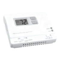
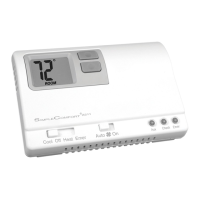
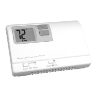
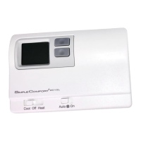
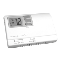
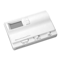
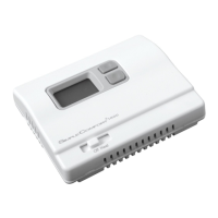
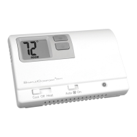
SC2311L
Non-Programmable Electronic Thermostat
Installation, Operation & Application Guide
For more information on our complete range of American-made
products – plus wiring diagrams, troubleshooting tips and more,
visit us at www.icmcontrols.com
• Congurable
• 2-Stage Heat/1-Stage Cool Systems
• Heat Pump Systems
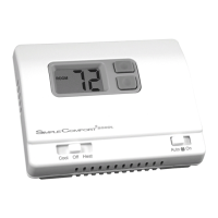
• Backlit Display
• Field Temperature Calibration
• Status Indicator Light
• Relay Outputs
(minimum voltage drop in thermostat)
• Ideally Suited for:
–
Residential (New Construction/Replacement)
– Light Commercial
Parts Diagram
Down
button
Up
button
Leftswitch
Resetswitch
RESET
LEFT
RIGHT
FP
R
C
W
O/B
Y
W2
E
G
Field
programming
pins
Rightswitch
Modeswitch
Fanswitch StatusLed
ELECTRICAL SHOCK HAZARD
– Turn off power at the main service panel by removing
the fuse or switching the appropriate circuit breaker to the OFF position before
removing the existing thermostat.
IMPORTANT:Thermostatinstallationmustconformtolocalandnationalbuildingand
electricalcodesandordinances.
Note: Mount the thermostat about four feet above the oor. Do not mount the thermostat
on an outside wall, in direct sunlight, behind a door, or in an area affected by a vent
or duct.
1.Turnoffpowertotheheatingandcoolingsystembyremovingthefuseorswitchingtheappropriate
circuitbreakeroff.
2. Toremovecover,insertandtwistacoinorscrewdriverintheslotsontopofthethermostat.
3. Putthermostatbaseagainstthewallwhereyouplantomountit(Besurewireswillfeedthrough
thewireopeninginthebaseofthethermostat).
4. Marktheplacementofthemountingholes.
5. Setthermostatbaseandcoverawayfromworkingarea.
6. Usinga3/16”drillbit,drillholesintheplacesyouhavemarkedformounting.
7. Useahammertotapsuppliedanchorsinmountingholes.
8. Alignthermostatbasewithmountingholesandfeedthecontrolwiresthroughwireopening.
9. Usesuppliedscrewstomountthermostatbasetowall.
10.Insertstripped,labeledwiresinmatchingwireterminals.See“WiringDiagrams”sectionofthis
manual.
CAUTION!
:
Besureexposedportionofwiresdoesnottouchotherwires.
11.Gentlytugwiretobesureofproperconnection.Doublecheckthateachwireisconnectedtothe
properterminal.
12.Replacecoveronthermostatbysnappingitinplace.
13.Turnonpowertothesystematthemainservicepanel.
14.Testthermostatoperationasdescribedin“TestingtheThermostat”.
To Install Thermostat
Terminal Designator Descriptions
R – 24VAChot
C – 24VACcommon
W1/O/B – Congurable
W1 – 1ststageheatfornon-hpsystems
O –coolactivereversingvalve
B –heatactivereversingvalve
Y –1ststagecool,1ststageheatforheatpumps
W2 – 2ndstageheatforheatpump,non-heatpump,andemergencyheat
E –1ststageheatforEmergencyHeatoperation
G –Fan
SC2311L Output Chart
1
ST
Cool 1
ST
Heat 2
ND
Heat
Heat/Cool Y,G W1,G* W1,W2,G*
Heat Pump (One Compressor) Y,G,O Y,G,B Y,W2,G,B
Emergency Heat HP N/A E,G E,W2,G
* G not energized when congured as a gas/oil system
TheSC2311Lthermostatiscongurablefordifferentsystems.Thecongurationdirectlyeffectsthe
outputs.
Usetheoutputcharttocorrectlycongureandwirethethermostattoyoursystem.
Second
HeatingControl
First
HeatingControl
Fan
Control
Electric Heat
Single Transformer
Second
HeatingControl
First
HeatingControl
Gas/Oil Heat
Single Transformer
Wiring Diagrams
CoolingControl
Fan
Control
Second
HeatingControl
First
HeatingControl
Fan
Control
CoolingControl
Single TransformerSingle Transformer
Single Compressor
2
nd
Stage
Heat
Reversing
Valve
Compressor
Emergency
Heat
Fan
Control
1. Temperature Scale (F or C)–ChooseFahrenheitorCelsius.
Presstheupordownbuttontoselect.
Pressthe RIGHT buttontoadvancetothenextscreen.
2. 1
st
Stage Temperature Differential(1°Fto5°F)(0.5°Cto2.5°C)
Setthenumberofdegreesbetweenyour“setpoint”temperatureandyour“turn
on”temperature.
Pressthe upordownbuttontosetdifferentialvalue.
PresstheRIGHTbuttontoadvancetothenextscreen.
Configuration Mode Settings
ThecongurationmodeisusedtosettheSC2311Ltomatchyourheating/coolingsystem.The
SC2311Lfunctionswithheatpump,airconditioning,gas,oilorelectricheatsystems.
ToconguretheSC2311L,performthefollowingsteps:
1. Removethecoverofthethermostatbygentlypullingononeofthetopcorners.
2. SimultaneouslyholdtheLEFTandRIGHTbuttonsinfor5secondswhiletheSC2311LisinOFF
mode.
3. Presstheupordownbuttontochangesettingswithineachscreen.
4. PresstheRIGHTbuttontoadvancetothenextscreen.
Note: The LEFT button will return you to the previous screen.
5. Toexitcongurationmode,slidetheModeswitchtoHeatorCool.
3. 2
nd
Stage Temperature Differential(1°Fto5°F)(0.5°Cto2.5°C)
Setthenumberofdegreesbetweenwhenstage1turnsonandwhenstage2
turnson.
Presstheupordownbuttontosetdifferentialvalue.
PresstheRIGHTbuttontoadvancetothenextscreen.
5. Heat Source (o,b,g,E)
Changebetween“o”Heatpumpcoolactive,“b”Heatpumpheatactive,“g”
(Gas)and“E”(Electric).
Presstheupordownbuttontosetheatsource.
PresstheRIGHTbuttontoadvancetothenextscreen.
4. Staged Off Outputs
Selectwhethertheoutputsforheatingandcoolingarestagedoff
independentlyoraresatisedsimultaneously.
1=outputsstagedoffindependently
0=outputsoffsimultaneously
Presstheupordown buttontoset.
Pressthe RIGHT buttontoadvancetothenextscreen.
6. Auxiliary Delay ON–(0-30minutes)–Setthedelaytimeinminutesforauxiliary
heattobelockedoutafteracallforsecondstage.Thisextrasavingsfeatureis
usedtotemporarilylockoutauxiliaryheatdevices,allowingjustheatpumptotry
tosatisfyheatcall.
Presstheupordownbuttontoselect.
PresstheRIGHT buttontoadvancetothenextscreen
7. Lockout (0°F-8°F)(0°C-4°C) –Selectthenumberofdegreessettemperature
canbechangedduringkeypadlockout
Pressthe upordownbuttontoselect.
Pressthe RIGHTbuttontoadvancetothenextscreen
.
8. Maximum Heat Setpoint(45°Fto90°F)(7°Cto32°C)
AdjusttocontrolthemaximumHeatsettemperatureallowed.
Presstheupordownbuttontoselect.
Pressthe RIGHTbuttontoadvancetothenextscreen.
9. Minimum Cool Setpoint(45°Fto90°F)(7°Cto32.0°C)
AdjusttocontroltheminimumCoolsettemperatureallowed.
Presstheupordownbuttontoselect.
Pressthe RIGHTbuttontoadvancetothenextscreen.
10.Room temperature offset(+9°Fto-9°F)(+4.5°Cto-4.5°C)
Adjusttocalibratedisplayedroomtemperaturetomatchactualroom
temperature.
Note: When not set to 0, ROOM will display.
Presstheupordownbuttontoselect.
Pressthe RIGHTbuttontoadvancetothenextscreen.
11.Maximum compressor cycles allowed per hour(-,2-6)
-=asmanyasneeded,and2-6=maximumcycles/hour
Presstheupordownbuttontoselect.
PresstheRIGHTbuttontoadvancetothenextscreen.
12.Cooling Fan Delay Off Time(0,30,60,90seconds)
Selectthefanpurgetimeforcooling.
Presstheupordownbuttontoselect.
Pressthe RIGHT buttontoadvancetothenextscreen.
13.Status Indicator Light(Lt0,1,2)
0=Statusindicatorneveron
1=Statusindicatoronwithrststage
2=Statusindicatoronwithsecondstage
Presstheupordownbuttontoselect.
Note: Red light indicates heating cycle and green light indicates cooling cycle.
SlidetheModeswitchtoHeatorCooltoexitconguration.