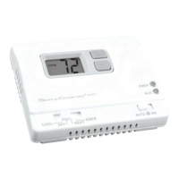
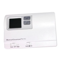
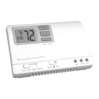
Parts Diagram
B
O
W2
G
E
Y1
Y2
R
L
C
W3
SW5 SW6 RESET FP
Check Light
Aux Light
Emergency Light
Fan Switch
Mode Switch
Conguration
Switches
Reset Switch
Large Backlit
Display
Up Button
Down Button
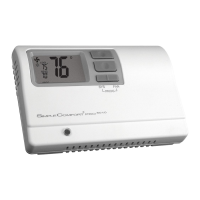
3-Stage Heat Pump
Manual Changeover
Hardwired
SC2211
Non-Programmable Electronic Thermostat
Installation, Operation & Application Guide
For more information on our complete range of American-made
products – plus wiring diagrams, troubleshooting tips and more,
visit us at www.icmcontrols.com
• Congurable
• ThreeStageHeatPumpSystems
• BacklitDisplay
• FieldCalibrationFeature
• RelayOutputs
(minimum
voltagedropinthermostat)
• IdeallySuitedfor:
–
Residential (New Construction/Replacement)
– Light Commercial
ELECTRICALSHOCKHAZARD
–Turnoffpoweratthemainservicepanelbyremoving
thefuseorswitchingtheappropriatecircuitbreakertotheOFFpositionbefore
removingtheexistingthermostat.
1. Turn off power to the heating and cooling system by removing the fuse or switching the
appropriate circuit breaker off.
2. Remove cover of old thermostat. This should expose the wires.
3. Label the existing wires with the enclosed wire labels before removing wires.
4. After labeling wires, remove wires from wire terminals.
5. Remove existing thermostat base from wall.
6. Refer to the following section for instructions on how to install this thermostat.
To Remove Existing Thermostat
Specifications
Electricalrating: • 24 VAC (18-30 VAC)
• 4 amp maximum total load
• 1 amp maximum per terminal
Temperaturecontrolrange:45°F to 90°F (7°C to 32°C) Accuracy: ± 1°F (± 0.5°C)
Systemcongurations: 3-stage heat, 2-stage cool heat pump
Timing:
Anti-short Cycle:
4 minutes
Backlight Operation: 10 seconds
Terminations: C, L, R, B, O, W2, G, E, Y1, Y2, W3
Important Safety Information
WARNING!
:
Alwaysturnoffpoweratthemainpowersupplybeforeinstalling,cleaning,
orremovingthermostat.
• This thermostat is for 24 VAC applications only; do not use on voltages over 30 VAC
• All wiring must conform to local and national electrical and building codes
• Do not use air conditioning when the outdoor temperature is below 50 degrees; this can damage
your A/C system and cause personal injuries
• Use this thermostat only as described in this manual
Package Contents/Tools Required
Packageincludes: SimpleComfort
®
2211 thermostat on base, thermostat cover, wiring labels, screws
and wall anchors, Installation, Operation and Application Guide
Toolsrequiredforinstallation: Drill with 3/16” bit, hammer, screwdriver
ELECTRICALSHOCKHAZARD
–Turnoffpoweratthemainservicepanelbyremoving
thefuseorswitchingtheappropriatecircuitbreakertotheOFFpositionbefore
removingtheexistingthermostat.
IMPORTANT: Thermostat installation must conform to local and national building and
electrical codes and ordinances.
Note: Mount the thermostat about four feet above the oor. Do not mount the thermostat
on an outside wall, in direct sunlight, behind a door, or in an area affected by a vent
or duct.
1. Turn off power to the heating and cooling system by removing the fuse or switching the appropriate
circuit breaker off.
2. To remove cover, insert and twist a coin or screwdriver in the slots on top of the thermostat.
3. Put thermostat base against the wall where you plan to mount it (Be sure wires will feed through
the wire opening in the base of the thermostat).
4. Mark the placement of the mounting holes.
5. Set thermostat base and cover away from working area.
6. Using a 3/16” drill bit, drill holes in the places you have marked for mounting.
7. Use a hammer to tap supplied anchors in mounting holes.
8. Align thermostat base with mounting holes and feed the control wires through wire opening.
9. Use supplied screws to mount thermostat base to wall.
10. Insert stripped, labeled wires in matching wire terminals. See “Wiring Diagrams” section of this
manual.
CAUTION!
:
Be sure exposed portion of wires does not touch other wires.
11. Gently tug wire to be sure of proper connection. Double check that each wire is connected to the
proper terminal.
12. Seal hole for wires behind thermostat with non-ammable insulation or putty.
13. Replace cover on thermostat by snapping it in place.
14. Turn on power to the system at the main service panel.
15. Test thermostat operation as described in “Testing the Thermostat”.
To Install Thermostat
Terminal Designator Descriptions
B – heat active reversing valve
O – cool active reversing valve
W2 – 2nd stage heat
G – Fan
E – 1st stage emergency heat
Y1 – 1st stage cool, 1st stage heat
Y2 – 2nd stage cool for 2 compressor systems
R – 24 VAC hot
L – Check indicator
C – 24 VAC common
W3 – 3rd stage heat
SC2211 Output Chart
1
ST
Cool 2
ND
Cool 1
ST
Heat 2
ND
Heat 3
RD
Heat
Heat Pump
Y1, G, O Y1, Y2, G, O Y1, G, B Y1, W2, G, B Y1, W2, W3, G, B
Emergency Heat Pump
N/A N/A E, G E, W2, G E, W2, W3, G
DualCompressor
HeatActiveHeatPump
withElectricBackup
Compressor #1
Emergency Heat
Fan
Heat Active
Reversing Valve
Malfunction Signal
Field Installed Jumper
Auxiliary Heat #1
Compressor #1
Emergency Heat
Fan
Cool Active
Reversing Valve
Malfunction Signal
DualCompressor
CoolActiveHeatPump
withElectricBackup
Field Installed Jumper
Wiring Diagram Conversions
SingleCompressor
HeatActiveHeatPump
withElectricBackup
Auxiliary Heat #2
Compressor #1
Emergency Heat
Fan
Auxiliary Heat #1
Heat Active
Reversing Valve
Malfunction Signal
Auxiliary Heat #2
Compressor #1
Emergency Heat
Fan
Auxiliary Heat #1
Cool Active
Reversing Valve
Malfunction Signal
SingleCompressor
CoolActiveHeatPump
withElectricBackup
Compressor #2 Compressor #2
Auxiliary Heat #1