Installation, Operation & Application Guide
For more information on our complete range of American-made
products – plus wiring diagrams, troubleshooting tips and more,
visit us at www.icmcontrols.com
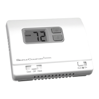
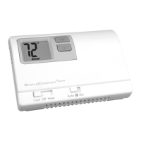
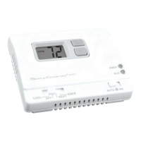
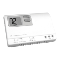
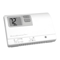
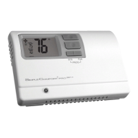
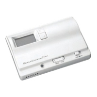
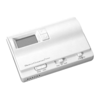
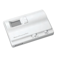
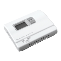
SC2000/SC2001
Non-Programmable Electronic Thermostats
• Permanent Memory
• Controls Single Stage Heating/
Cooling Systems
• Single Stage Heat Pump Systems
• Compatible with Gas, Oil or Electric
Systems
• Millivolt and Hydronic (water or
steam) System Compatible
• Mercury-Free, Environmentally Safe
SET
ROOM
LO BAT
DIFF
Low battery signal
Temperature
differential setting
Room temperature
Room temperature
setpoint
Specifications
SC2000 SC2001
Input: Input:
• Voltage: Millivolt to 30 VAC/VDC • Voltage: 18-30 VAC
• DCPower: 3 volts (2 “AA” alkaline batteries included)
Output:
• Maximum: 1 amp per terminal (3 amp total for all terminals)
• Temperaturecontrolranges:45°F to 90°F (7°C to 32°C)
Accuracy: ± 1°F (± 0.5°C)
• Differentialrange:1°F to 3°F (0.5°C to 1.5°C)
• Systemcongurations:
Single-stage heat, single-stage cool or single-stage heat
pump, gas, oil, electric
• Compressordelay:4 minutes
• Terminations(SC2000): RC, RH, W, Y, O, B, G
• Terminations(SC2001): R, W, Y, O, B, G, C
Important Safety Information
• Always turn off the thermostat before installing, removing, cleaning, or servicing; turn off the power at the main
power source by unscrewing fuse or switching off circuit breaker
• Do not switch to “Cool” if room temperature is below 50
°
F (10
°
C); this could damage your A/C system and cause
injury
• Do not install on voltages higher that 30 VAC
• All wiring must conform to local and national building and electrical codes and ordinances
• While cleaning, do not get soap directly on thermostat switches or LCD readout; only use a damp cloth with a mild
soap to wipe outside of thermostat cover
General Description
• The SimpleComfort
®
thermostat is a digital, mercury-free, non-programmable, electronic thermostat
• Compatible with single-stage heating systems, heating/cooling systems, and heat pump systems; works with
gas, oil, or electric systems
• Compatible as a master thermostat in zoned system applications
• Freeze Protection Feature (SC2000 only): Protects pipes from freezing! If the room temperature drops to 40
°
F,
the thermostat automatically turns on the heat; the thermostat must be in the Heat position; works even if the
batteries are dead
• Built-in Compressor Protection for Air Conditioners: To protect the A/C’s compressor, there is a 4-minute
delay between the system turning off and the A/C starting
• System Customization: Choose Fahrenheit or Celsius display; three available temperature differential
settings
Package Contents/Tools Required
Packageincludes: SimpleComfort
®
non-programmable thermostat on base, thermostat cover, wiring labels, screws
and wall anchors, batteries (if applicable), Installation, Operation and Application Guide.
Toolsrequiredforinstallation: Drill with 3/16” bit, hammer, screwdriver.
To Remove Existing Thermostat
ELECTRICALSHOCKHAZARD
–Turnoffpoweratthemainservicepanelbyremovingthefuse
orswitchingtheappropriatecircuitbreakertotheOFFpositionbeforeremovingtheexisting
thermostat.
1. Turn off power to the heating and cooling system by removing the fuse or switching off the appropriate circuit
breaker.
2. Remove cover of old thermostat. This should expose the wires.
3. Label the existing wires with the enclosed wire labels before removing wires.
4. After labeling wires, remove wires from wire terminals.
5. Remove existing thermostat base from wall.
6. Refer to the following section for instructions on how to install this thermostat.
To Install Thermostat
ELECTRICALSHOCKHAZARD
–Turnoffpoweratthemainservicepanelbyremovingthefuse
orswitchingtheappropriatecircuitbreakertotheOFFpositionbeforeremovingtheexisting
thermostat.
IMPORTANT: Thermostat installation must conform to local and national building and electrical codes and
ordinances.
Note:
Mount the thermostat about ve feet above the oor. Do not mount the thermostat on an outside
wall, in direct sunlight, behind a door, or in an area affected by a vent or duct.
1. Turn off power to the heating and cooling system by removing the fuse or switching off the appropriate circuit
breaker. Move the Cool/OFF/Heat switch to OFF
.
2. Move the FANAUTO/ON switch to AUTO.
3. To remove cover, insert and twist a coin or screwdriver in the slots on the top of the thermostat.
4. Put thermostat base against the wall where you plan to mount it (Be sure wires will feed through the wire opening
in the base of the thermostat).
5. Mark the placement of the mounting holes.
6. Set thermostat base and cover away from working area.
7. Using a 3/16” drill bit, drill holes in the places you have marked for mounting.
8. Use a hammer to tap supplied anchors into mounting holes.
9. Align thermostat base with mounting holes and feed the control wires through wire opening.
10. Use supplied screws to mount thermostat base to wall.
CAUTION!
:
Be sure exposed portion of wires does not touch other wires.
11. Tighten screws on terminal block. Gently tug wire to be sure of proper connection. Double check that each wire
is connected to the proper terminal.
CAUTION!
:
Remove RH/RC jumper for 2 transformer system (SC2000 only).
12. Set the fanjumper to electric or gas/oil.
13. Install two “AA” alkaline batteries (SC2000 only).
14. Replace cover on thermostat by snapping it in place.
15. Turn on power to the system at the main service panel.
Installing and Changing Batteries (SC2000 only)
If your LCD is blank, or displaying LOBAT, the batteries are not installed or need to be changed. We suggest you
change the batteries at least once a year and whenever the LOBATwarning displays.
Step1: Move the Cool/Off/Heat switch into the Off position.
Step2: Move the FanAuto/On switch into the Auto position.
Step3: Remove the cover, and install the two “AA” alkaline batteries into the battery compartment. Proper battery
installation is important! Make sure the positive ends of the batteries match the positive terminals in the
battery compartment.
If the display is on, the batteries are installed properly.
Replacing Wiring Labels
Replace the old labels with the enclosed new labels:
Old New Type
F, G G Fan control relay
O O Cool active reversing valve
B B Heat active reversing valve
Y, Y6 Y Cooling control
H, W, 4 W
Heating control
C Transformer, common side
M, 4, RH, RS, R R Transformer, hot side
C Y or C
If the C terminal is the cooling control, connect to Y terminal; if it is the
common side of the transformer, connect to C terminal
SC2000 – ZoneValve/DamperMotorSystems
3-Wire,ZoneValve/DamperMotorSystem
2-Wire,ZoneValve/DamperMotorSystem
RH RC W Y B O G RH RC Y B GRH RC Y B O G
RH RC W Y O G RH RC W Y O GRH RC W Y B O
Zone 1 Zone 3Zone 2
Zone 1 Zone 3Zone 2
24 VAC
*
Use appropriate
size, single pole/
double throw relay
Note:
Differential temperature may need to be increased for zone/damper system
* *
Wiring Diagrams
4-Wire,SingleTransformer
HOT
120 VAC 24 VAC
Transformer
Heating
Control
HOT
RH
RC
W
Y
B
O
G
120 VAC 24 VAC
Remove
Pre-Installed
Jumper
Cooling
Control
Fan
Control
(Cooling)
Transformer
HOT
120 VAC 24 VAC
T
H
E
R
M
O
S
T
A
T
Note:
Both transformers must be in phase
5-Wire,TwoTransformer
Pre-Installed Jumper
RH RC RH RC
Cooling
Control
Fan
Control
SC2000 – Heating/Cooling
Parts Diagrams
SC2000 SC2001
Electric/Gas
Jumper
Mode
Switch
Fan
Switch
Electric/Gas
Jumper
Mode
Switch
Fan
Switch
Freeze
Switch
RH RC Jumper
SC2001
SC2000
RWYBOG
GAS
ELEC
RCRHWYBOG
GAS
ELEC
Battery Compartment
For Vertical and Horizontal Models
T
H
E
R
M
O
S
T
A
T
RH
RC
W
Y
B
O
G