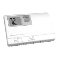
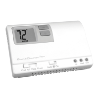
1 Heat/1 Cool
Manual Changeover
Battery or Hardwire
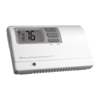
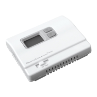
SC2010 N/L
Non-Programmable Electronic Thermostat
Installation, Operation & Application Guide
For more information on our complete range of American-made
products – plus wiring diagrams, troubleshooting tips and more,
visit us at www.icmcontrols.com
• Congurable
• SingleStageHeat/CoolSystems
• SingleStageHeatPumpSystems
• LargeDisplayWithBacklight(SC2010L)
• SelectableFahrenheitorCelsius
• CompatiblewithGas,Oil,orElectric
• SimpleSet™FieldProgramming
• RelayOutputs
(minimumvoltagedropinthermostat)
• IdeallySuitedfor:
– Residential (New Construction/Replacement)
– Light Commercial
Important Safety Information
WARNING!
:
Alwaysturnoffpoweratthemainpowersupplybeforeinstalling,cleaning,
orremovingthermostat.
•Thisthermostatisfor24VACapplicationsonly;donotuseonvoltagesover30VAC
•Donotshortacrossterminalsofgasvalveorsystemcontroltotestoperation;thiswilldamageyour
thermostatandvoidyourwarranty
•Allwiringmustconformtolocalandnationalelectricalandbuildingcodes
•Donotuseairconditioningwhentheoutdoortemperatureisbelow50degrees;thiscandamage
yourA/Csystemandcausepersonalinjuries
•Usethisthermostatonlyasdescribedinthismanual
Specifications
Electricalrating:
•24VAC(18-30VAC)
•3.0VDC(2“AAA”batteries)
•1ampmaximumperterminal
•3ampmaximumtotalload
Temperaturecontrolrange:45°Fto90°F(7°Cto32°C)Accuracy:±1°F(±0.5°C)
Systemcongurations:1-stageheat,1-stagecool,heatpump,gas,oil,electric
Timing:
Anti-shortCycle:
4minutes
Backlight Operation (Note:withSC2010Lonly)
Terminations:G,B,O,Y,RH,RC,W,C
Package Contents/Tools Required
Packageincludes: SC2010N/Lthermostatonbase,thermostatcover,wiringlabels,screwsandwall
anchors,2“AAA”batteries,Installation,OperationandApplicationGuide
Toolsrequiredforinstallation:Drillwith3/16”bit,hammer,screwdriver
ELECTRICALSHOCKHAZARD
–Turnoffpoweratthemainservicepanelbyremoving
thefuseorswitchingtheappropriatecircuitbreakertotheOFFpositionbefore
removingtheexistingthermostat.
1. Turnoffpowertotheheatingandcoolingsystembyremovingthefuseorswitchingtheappropriate
circuitbreakeroff.
2. Removecoverofoldthermostat.Thisshouldexposethewires.
3. Labeltheexistingwireswiththeenclosedwirelabelsbeforeremovingwires.
4. Afterlabelingwires,removewiresfromwireterminals.
5. Removeexistingthermostatbasefromwall.
6. Refertothefollowingsectionforinstructionsonhowtoinstallthisthermostat.
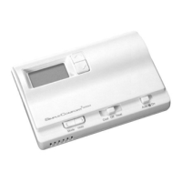
To Remove Existing Thermostat
Parts Diagram
SC2010 N/L
Leftbutton
Rightbutton
Downbutton
Upbutton
Fieldprogrammingpins
RC/RHJumper
Leftswitch
Reset switch
Gas/Elec
Battery
compartment
High
Temperature
Protection
Freeze
Protection
Mode switch
Fanswitch
HP/Non-Heat
Jumper
Right switch
To Install Thermostat
ELECTRICALSHOCKHAZARD
–Turnoffpoweratthemainservicepanelbyremoving
thefuseorswitchingtheappropriatecircuitbreakertotheOFFpositionbefore
removingtheexistingthermostat.
IMPORTANT: Thermostat installation must conform to local and national building and
electrical codes and ordinances.
Note: Mount the thermostat about ve feet above the oor. Do not mount the thermostat on an
outside wall, in direct sunlight, behind a door, or in an area affected by a vent or duct.
1. Turnoffpowertotheheatingandcoolingsystembyremovingthefuseorswitchingthe
appropriatecircuitbreakeroff.
2. Toremovecover,pullgentlyattheseamatthetop.
3. Putthermostatbaseagainstthewallwhereyouplantomountit(Besurewireswillfeedthrough
thewireopeninginthebaseofthethermostat).
4. Marktheplacementofthemountingholes.
5. Setthermostatbaseandcoverawayfromworkingarea.
6. Usinga3/16”drillbit,drillholesintheplacesyouhavemarkedformounting.
7. Useahammertotapsuppliedanchorsinmountingholes.
8. Alignthermostatbasewithmountingholesandfeedthecontrolwiresthroughslitinthermal
intrusionbarrierandintowireopening.
9. Usesuppliedscrewstomountthermostatbasetowall.
10.Insertstripped,labeledwiresinmatchingwireterminals.
CAUTION!: Be sure exposed portion of wires does not touch other wires.
11.Gentlytugwiretobesureofproperconnection.Doublecheckthateachwireisconnectedtothe
properterminal.
12.Placegas/elecjumperincorrectposition.
gas=gas/oilsystems
elec=electricheatorheatpumpsystems
13.RemoveRC/RHjumperfor2-transformersystems.
14.Non-heatpumpjumpermustbeinNon-HPunlessthesystemisaheatpump.
15.Insert2“AAA”batteriesintobatteryholder.Orientthemintheproperdirection.
16.Turnonpowertothesystematthemainservicepanel.
17.Congurethermostat(seeCongurationModeSettings)tomatchthetypeofsystemyouhave.
18.Replacecoveronthermostatbysnappingitinplace.
19.Testthermostatoperationasdescribedin“TestingtheThermostat”.
Wiring Diagrams
Commonwireconnectionoptionalwithbatteriesinstalled.
Hardwired
4-Wire,SingleTransformer
Hardwired
3-Wire,SingleTransformer
Optional Optional
Hardwired
4or5-Wire,SingleTransformer
Optional
Hardwired
5-Wire,TwoTransformer
(Both transformers must be in phase)
IMPORTANT:Beforewiring,removepre-installed
RC/RHjumper.
Heating
Transformer
Cooling
Transformer
Common wire connection optional with
batteriesinstalled.
Hardwired
CoolorHeatActiveReversingValve
Commonwireconnectionoptionalwithbatteries
installed.
Note: Non-HP jumper must be installed on the
HP pin for heat pump systems
Optional
Hardwired
4-Wire,SingleTransformer
Common wire connection optional with
batteriesinstalled.
Optional