EasyManua.ls Logo

ICM Controls SC 2311 - User Manual

ICM Controls SC 2311
28 pages
Print Icon
To Next Page IconTo Next Page
Loading...
2 Heat/1 Cool
Manual Changeover
Hardwired
SC 2311
Non-Programmable Electronic Thermostat
Installation, Operation & Application Guide
For more information on our complete range of American-made
products – plus wiring diagrams, troubleshooting tips and more,
visit us at www.icmcontrols.com
Configurable
2-Stage Heat/1-Stage Cool Systems
Heat Pump Systems
Backlit Display
Field Temperature Calibration
Filter Check
Status Indicator Light
Relay Outputs
(minimum voltage drop in thermostat)
Ideally Suited for:
Residential (New Construction/Replacement)
Light Commercial

Questions and Answers

  • S
    Samantha WoodAug 15, 2025
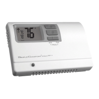
    What to do if the ICM Controls Thermostat displays 'filter'?
    • J
      Joy WalkerAug 15, 2025
      The 'filter' message appears when the fan run time exceeds the filter check time set in the configuration. To clear the filter warning and reset the counter to zero, simultaneously press the up and down buttons for 5 seconds.
  • S
    Sean GarciaAug 18, 2025
    How to fix no display on my ICM Controls SC 2311 Thermostat?
    • L
      Larry BrownAug 18, 2025
      If there is no display on your ICM Controls Thermostat, check for 24 VAC at the thermostat. The display will be blank if 24 VAC is not present.
  • K
    Kayla TrujilloAug 22, 2025
    Why is the room temperature on my ICM Controls SC 2311 not correct?
    • R
      Rachel JamesAug 22, 2025
      If the room temperature displayed on your ICM Controls Thermostat is incorrect, first verify that the wall hole behind the thermostat is plugged with putty or insulation. You can also calibrate the thermostat.
  • P
    Paula MarshAug 26, 2025
    How to stop my ICM Controls SC 2311 fan from running continuously?
    • M
      michelle46Aug 26, 2025
      To stop the fan from running continuously, check the fan On/Auto switch. If it's in the ON position, the indoor fan will run continuously.
  • J
    Jeanne JohnsonAug 28, 2025
    What to do if the system fan on my ICM Controls SC 2311 does not come on properly?
    • T
      Tracy DixonAug 28, 2025
      If the system fan is not working correctly, verify the wiring is correct and check the configuration.
  • M
    Micheal RoseAug 31, 2025
    How to adjust the temperature settings if my ICM Controls SC 2311 turns on and off too frequently?
    • M
      Melissa FisherAug 31, 2025
      If your ICM Controls Thermostat is turning on and off too frequently, adjust the temperature differential.
  • R
    robertmuellerSep 4, 2025
    What does 'ROOM' display mean on my ICM Controls SC 2311?
    • J
      John WestSep 4, 2025
      The 'ROOM' display indicates that the room temperature offset is not zero.
  • C
    Christine StevensSep 8, 2025
    What to do if my ICM Controls SC 2311 Thermostat has a problem not listed in the manual?
    • A
      andersenbarbaraSep 8, 2025
      If you are experiencing a problem not listed, press the Reset button once. This will refresh the display and reset the anti-short cycle timing to zero.
  • J
    jamesturnerSep 12, 2025
    What does 'EH' mean when it displays on my ICM Controls SC 2311 Thermostat when a button is pressed?
    • K
      Kimberly JamesSep 12, 2025
      The 'EH' display indicates that the thermostat is in Emergency Heat mode.

Summary

Parts Diagram Overview

Product Specifications

Critical Safety Precautions

Package Contents and Installation Tools

Removing Existing Thermostat

Installing the New Thermostat

Terminal Designator Explanations

System Wiring Diagrams

Cooling Only System Wiring

Wiring diagrams for cooling-only systems.

Heating and Cooling System Wiring

Wiring diagrams for systems with both heating and cooling.

Heating Only System Wiring

Wiring diagrams for heating-only systems.

Heat Pump System Wiring

Wiring diagrams specific to heat pump systems.

Wiring Diagram Conversion Guides

Carrier Split Stream Conversion

Guide for converting to Carrier split stream systems.

Coleman 3000 Series Conversion

Guide for converting to Coleman 3000 series systems.

ComfortMaker CYC Series Conversion

Guide for converting to ComfortMaker CYC series systems.

Heil-Quaker 867;PH50 Series Conversion

Guide for converting to Heil-Quaker 867/PH50 series systems.

Payne Reliant;Endura Conversion

Guide for converting to Payne Reliant/Endura systems.

Rheem;Ruud Series Conversion

Guide for converting to Rheem/Ruud series.

Goodman;Janitrol;Trane Conversion

Guide for converting to Goodman, Janitrol, Trane/American Standard heat pumps.

York E1 CS;E1 FB;E1 FH Conversion

Guide for converting to York E1CS, E1FB, E1FH systems.

Lennox CB19 Conversion

Guide for converting to Lennox CB19 heat pump systems.

Lennox HP19;HP20 Conversion

Guide for converting to Lennox HP19 and HP20 heat pump systems.

Thermostat Configuration Mode

Heat Pump System Configuration

Configure system type (heat pump or non-heat pump).

Heat Source Selection

Select heat source (Gas or Electric) for non-heat pump systems.

Reversing Valve Configuration

Set reversing valve mode (O-Active or B-Active) for heat pumps.

Temperature Scale Setting

Choose between Fahrenheit or Celsius temperature scales.

1 st Stage Differential Setting

Set differential for first stage heating/cooling activation.

2 nd Stage Differential Setting

Set differential for second stage heating activation.

Minimum Cool Setpoint Control

Control the minimum allowed cool set temperature.

Maximum Heat Setpoint Control

Control the maximum allowed heat set temperature.

Room Temperature Calibration

Calibrate displayed room temperature for accuracy.

Compressor Cycle Limit

Set the maximum number of compressor cycles per hour.

Filter Check Time Setup

Set fan run time before filter warning.

Status Indicator Light Setup

Configure the status indicator light behavior.

Thermostat Testing Procedures

Cooling Function Test

Steps to test the cooling function of the thermostat.

Heating Function Test

Steps to test the heating function of the thermostat.

Fan Operation Test

Steps to test the indoor fan operation.

Thermostat Operating Modes

Off Mode Operation

Thermostat is inactive, no heating or cooling.

Cool Mode Operation

Thermostat controls the cooling system.

Heat Mode Operation

Thermostat controls the heating system.

Emergency Heat Mode Operation

Auxiliary heat operates; compressor disabled for heat pumps.

Emergency Heat Mode Entry;Exit

Procedures for activating and deactivating emergency heat.

Troubleshooting Guide

Limited One-Year Warranty

ICM Controls SC 2311 Specifications

General IconGeneral
Voltage24 VAC
Temperature Accuracy±1°F (±0.5°C)
DisplayLCD
BacklightYes
Stages of Cooling1
Stages2 Heat / 1 Cool
Fan SwitchAuto, On
Hold FunctionYes
Fan ControlYes
System ModeHeat, Cool, Off
Temperature Range45°F to 90°F (7°C to 32°C)
CompatibilityGas, Oil, Electric systems
Switch PositionsHeat, Cool, Off
Number of Programs4 Programs per Day
Dimensions1.1 inches
Stages of Heating2 Heat

Related product manuals