Installation, Operation & Application Guide
For more information on our complete range of American-made
products – plus wiring diagrams, troubleshooting tips and more,
visit us at www.icmcontrols.com
Package Contents/Tools Required
Package includes: SC5010 PROthermostatonbase,thermostatcover,wiringlabels,screwsandwallanchors,2
“AAA”batteries,Installation,OperationandApplicationGuide
Tools required for installation:Drillwith3/16”bit,hammer,screwdriver
To Remove Existing Thermostat
ELECTRICAL SHOCK HAZARD
– Turn off power at the main service panel by removing the fuse
or switching the appropriate circuit breaker to the OFF position before removing the existing
thermostat.
1. Turnoffpowertotheheatingandcoolingsystembyremovingthefuseorswitchingtheappropriatecircuit
breakeroff.
2. Removecoverofoldthermostat.Thisshouldexposethewires.
3. Labeltheexistingwireswiththeenclosedwirelabelsbeforeremovingwires.
4. Afterlabelingwires,removewiresfromwireterminals.
5. Removeexistingthermostatbasefromwall.
6. Refertothefollowingsectionforinstructionsonhowtoinstallthisthermostat.
1 Heat/1 Cool
Auto Changeover
Battery or Hardwire
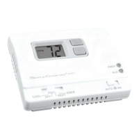
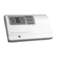
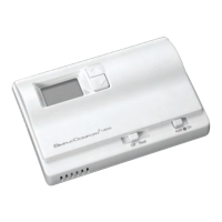
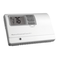
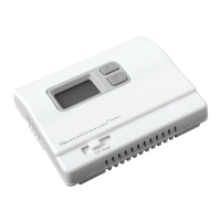
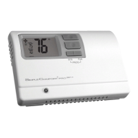
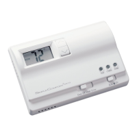
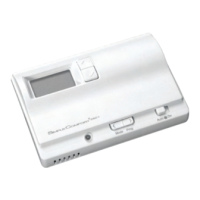
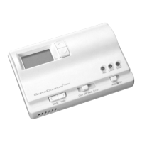
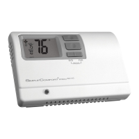
SC5010
Programmable Electronic Thermostat
• 7-Day, 5-2-Day or 5-1-1-Day Programmable
• Congurable
• Single Stage Heat/Cool Systems
• Single Stage Heat Pump Systems
• Large Display With Backlight
• Selectable Fahrenheit or Celsius
• Compatible with Gas, Oil, or Electric
• SimpleSet™ Field Programming
• Status Indicator Light
• Relay Outputs
(minimum voltage drop in thermostat)
• Remote Sensor Compatible
• Ideally Suited for:
– Residential(NewConstruction/Replacement)
– LightCommercial
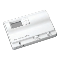
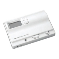
Parts Diagram
Congurationswitch
Resetswitch
Fieldprogrammingpins
RC/RHJumper
RCGW
O/B
YS2S1 CRH
CONFIGRESET
FP
RC
RH
Icon Descriptions
Coolingoperationicon
Fanoperationicon
Heatingoperationicon
Lockmodeactivated
Roomtemperature
offsetactivated
Important Safety Information
WARNING!
:
Always turn off power at the main power supply before installing, cleaning, or removing
thermostat.
• Thisthermostatisfor24VACapplicationsonly;donotuseonvoltagesover30VAC
• Donotshortacrossterminalsofgasvalveorsystemcontroltotestoperation;thiswilldamageyourthermostat
andvoidyourwarranty
• Allwiringmustconformtolocalandnationalelectricalandbuildingcodes
• Donotuseairconditioningwhentheoutdoortemperatureisbelow50degrees;thiscandamageyourA/Csystem
andcausepersonalinjuries
• Usethisthermostatonlyasdescribedinthismanual
Specifications
Electrical rating:•24VAC(18-30VAC)
•3.0VDC(2“AAA”batteries)
•1ampmaximumperterminal
•3ampmaximumtotalload
Temperature control range: 45°Fto90°F(7°Cto32°C)Accuracy:±1°F(±0.5°C)
System congurations:1-stageheat,1-stagecool,heatpump,gas,oil,electric
Timing:
Anti-shortCycle:
4minutes
BacklightOperation:5secondswhenconguredON
Terminations:S1,S2,Y,W/O/B,G,RC,RH,C
Hardwired
5-Wire, Two Transformer
(Both transformers must be in phase)
Hardwired
4 or 5-Wire, Single Transformer
Fan
Control
IMPORTANT:Beforewiring,removepre-installed
RC/RHjumper.
To Install Thermostat
ELECTRICAL SHOCK HAZARD
– Turn off power at the main service panel by removing the fuse
or switching the appropriate circuit breaker to the OFF position before removing the existing
thermostat.
IMPORTANT:Thermostat installation must conform to local and national building and electrical codes and
ordinances.
Note:Mount the thermostat about ve feet above the oor. Do not mount the thermostat on an outside wall, in
direct sunlight, behind a door, or in an area affected by a vent or duct.
1. Turnoffpowertotheheatingandcoolingsystembyremovingthefuseorswitchingtheappropriatecircuit
breakeroff.
2. Toremovecover,pullgentlyattheseamatthetop.
3. Putthermostatbaseagainstthewallwhereyouplantomountit(Besurewireswillfeedthroughthewireopening
inthebaseofthethermostat).
4. Marktheplacementofthemountingholes.
5. Setthermostatbaseandcoverawayfromworkingarea.
6. Usinga3/16”drillbit,drillholesintheplacesyouhavemarkedformounting.
7. Useahammertotapsuppliedanchorsinmountingholes.
8. Alignthermostatbasewithmountingholesandfeedthecontrolwiresthroughslitinthermalintrusionbarrierand
intowireopening.
9. Usesuppliedscrewstomountthermostatbasetowall.
10. Insertstripped,labeledwiresinmatchingwireterminals.
CAUTION!
:Be sure exposed portion of wires does not touch other wires.
11. Gentlytugwiretobesureofproperconnection.Doublecheckthateachwireisconnectedtotheproper
terminal.
12. Insert2“AAA”batteriesintobatteryholder.Orientthemintheproperdirection.
13. Turnonpowertothesystematthemainservicepanel.
14. Congurethermostattomatchthetypeofsystemyouhave.
15. Replacecoveronthermostatbysnappingitinplace.
16. Testthermostatoperationasdescribedin“TestingtheThermostat”.
Wiring Diagrams
Hardwired
3-Wire, Single Transformer
Hardwired
4-Wire, Single Transformer
* Commonwireconnection
optionalwithbatteries
installed.
Hardwired – Cool or Heat Active Reversing Valve
Hardwired – 4-Wire, Single Transformer
Configuration Mode Settings
ThesetupscreensforCongurationModeareasfollows:
2. Temperature Differential (1°F to 5°F) (0.5°C to 2.5°C) –Setthenumberofdegrees
betweenyour“setpoint”temperatureandyour“turnon”temperature.
Presstheupordownbuttontosetdifferentialvalue.
Presstheright buttontoadvancetothenextscreen.
1. Temperature Scale (F or C) –ChooseFahrenheitorCelsius.
Presstheupordownbuttontoselect.
Pressthe
right
buttontoadvancetothenextscreen.
3. Deadband (1°F - 9°F) (1°C - 5°C) –Settheminimumnumberofdegreesbetweenyour
heatsettemperatureandyourcoolsettemperatureinAutochangeovermode.
Presstheupordownbuttontosetdeadbandvalue.
Presstherightbuttontoadvancetothenextscreen.
Installing and Changing Batteries
IfyourLCDisblank,ordisplayingLO BAT,thebatteriesarenotinstalledorneedtobechanged.Wesuggestyou
changethebatteriesatleastonceayear,orwhenevertheLO BAT warningdisplays.
Removethecover,andinstallthetwo“AAA”alkalinebatteriesintothebatterycompartment.Properbattery
installationisimportant!Makesurethepositiveendsofthebatteriesmatchthepositiveterminalsinthebattery
compartment.
Batterieswillprovidepowertomaintaintheclockduringapowerloss.
Configuration Mode
OFF
PM
1. VerifytheSC5010isintheOFFmode.
PresstheSYS(left)buttonuntiloffmodedisplays.
ThecongurationmodeisusedtosettheSC5010tomatchyourheating/coolingsystem.TheSC5010functions
withheatpump,airconditioning,gas,oilorelectricheatsystems.
ToconguretheSC5010,performthefollowingsteps:
2. Removethecoverofthethermostatbygentlypullingnearoneofthe
cornersatthetopofthethermostat.
Note:Do not force open. Use a small coin or slotted screwdriver to release tabs if necessary.
Presstheupordownbuttontochangesettingswithineachscreen.
Down
button
Up
button
Toexitcongurationmode,presstheCONFIGswitchfor1second.
Presstherightbuttontoadvancetothenextscreen.
Note:Pressing the
left
button will return you to the previous screen.
Left
button
Right
button
3. PresstheCONFIGbuttonfor1secondwhiletheSC5010isinOFF mode.
CONFIG
5. Lockout (0-8°, NITE, COOL-HEAT) –Selectthenumberofdegreessettemperature
canbechangedduringkeypadlockoutorselecttolockoutduringNITEperiodonly.
COOL-HEATlockoutallowsadjustmentofthesettemperaturestothemaximum
heatsettemperatureselectedinStep6andminimumcoolsettemperatureselectedin
Step7.
Note:The mode cannot be changed when the thermostat is locked.
Presstheupordownbuttontoselect.
Presstherightbuttontoadvancetothenextscreen.
Choose System
Reversing
Valve Active
Number of Com-
pressors
Type of
Heat
Heat Pump
HP O 1
HP b 1
Non-Heat
Pump
Heat Gas
Heat Electric
Presstheupordownbuttontoselect.
Presstherightbuttontoadvancetothenextscreen.
4. System –Setforheatpump,non-heatpump,reversingvalveoperationandnumberofcompressorinyour
system
* Commonwireconnection
optionalwithbatteries
installed.
* Commonwireconnection
optionalwithbatteries
installed.
6. Maximum Heat Setpoint(45°Fto90°F)(7°Cto32°C)
Adjusttocontrolthemaximumheatsettemperatureallowed.
Presstheupordownbuttontoselect.
Presstherightbuttontoadvancetothenextscreen.
7. Minimum Cool Setpoint(45°Fto90°F)(7°Cto32°C)
Adjusttocontroltheminimumcoolsettemperatureallowed.
Presstheupordownbuttontoselect.
Presstherightbuttontoadvancetothenextscreen.
8. Room Temperature Offset(+9°Fto-9°F)(+4.5°Cto-4.5°C)
Adjusttocalibratedisplayedroomtemperaturetomatchactualroomtemperature.
Note:When not set to 0, will display
Presstheupordownbuttontoselect.
Presstherightbuttontoadvancetothenextscreen.
9. Maximum Cycles Allowed Per Hour(--,2-6)
--=asmanyasneeded,2-6=maximumcycles/hour
Presstheupordownbuttontoselect.
Presstherightbuttontoadvancetothenextscreen.
OFF
11. Cooling Fan Delay Off Time(0,30,60,90seconds)
Selectthefanpurgetimeforcooling.
Presstheupordownbuttontoselect.
Presstherightbuttontoadvancetothenextscreen.
10. Temperature Sensor(1-4)
1. Onlyon-boardsensordeterminesroomtemperature.
2. Onlyremotesensordeterminesroomtemperature.
3. Averagetemperatureofon-boardandremotesensor.
4. Onlyon-boardsensorwillbeuseduntilNITEperiod,andthenonlyremotesensor
isused.
Presstheupordownbuttontoselect.
Presstherightbuttontoadvancetothenextscreen.
1.Removecoverfromremotesensorhousing.
2.Selectanappropriatelocationformountingtheremotesensor.
3.Mountremotesensorunitusinghardwareprovided.
4.Installtwostrandshieldedwirebetweenremotesensorandthermostat.Shieldedwiremustbeused.Do notrun
remotesensorwireinconduitwithotherwires.
•Wire 1shouldrunbetweentheS1terminalonthe
thermostatandtheS1terminalontheremotesensor
•Wire 2shouldrunbetweentheS2terminalonthe
thermostatandtheS2terminalontheremotesensor
•ConnecttheshieldingofthewiretotheS2terminalon
thethermostat
5.Congurethethermostattooperatewiththeremote
sensor(seeCongurationModesetting10).
Remote or Outdoor Sensor Installation (Optional)
Note:Remote or outdoor sensor reading can be
displayed by simultaneously pressing the Down
and SYS buttons.
ACC-RT104
RemoteSensor
(Optional)