Do you have a question about the Icom IC-02AT and is the answer not in the manual?
Provides overall technical specifications for the transceiver.
Details output power, emission mode, and modulation characteristics.
Outlines sensitivity, selectivity, and audio output parameters.
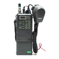
Identifies and illustrates controls on the top, front, and rear panels.
Explains frequency display indicators and keypad functions.
Details function keys, switches, connectors, and indicators.
Explains the functional blocks of the receiver system.
Details the functional blocks of the transmitter system.
Describes the Phase Locked Loop circuit for frequency synthesis.
Covers voltage regulation, power switching, and microcomputer logic.
Explains circuits for lamps, beeps, tone units, and switching.
Presents a high-level block diagram of the transceiver's architecture.
Shows the physical placement of components on the IC-02AT board.
Shows the physical placement of components on the IC-02E board.
Provides steps for removing the transceiver case and top panel.
Details procedures for replacing speaker/microphone and PTT spring assemblies.
Details the disassembly process for the unit's bottom assembly.
Lists required test equipment and essential initial checks.
Outlines procedures before servicing and methods for checking operation.
Details step-by-step procedures for aligning and adjusting circuits.
Illustrates component placement on the main circuit board.
Shows component placement on the PLL circuit board.
Illustrates component placement on the logic circuit board.
Shows component layouts for tone and tone call circuit boards.
Details diode matrix configurations for different versions.
Provides DC voltage readings for transistors in transmit and receive modes.
Illustrates voltage distribution across various circuit units.
Guides users through diagnosing and resolving power-on issues.
Helps identify and fix PLL lock failure problems.
Provides troubleshooting steps for reception and transmit power issues.
Details specifications for MPU, PLL, FM IF, and PA ICs.
Covers specifications for regulators, PA modules, and driver ICs.
Details specifications for logic gates, comparators, and tone generators.
Lists all components for the main unit with part numbers.
Lists all components for the PLL unit with part numbers.
Lists components for logic, tone, and tone call units.
Provides the complete circuit schematic for the transceiver.
| Modulation | FM |
|---|---|
| Power Output | 1.5 W |
| Memory Channels | 10 |
| Power Supply | 9.6 VDC |
| Type | Handheld |
| Receiver Sensitivity | 0.25 µV |