EasyManuals Logo

Icom IC-7100 Service Manual

Icom IC-7100
84 pages
To Next Page IconTo Next Page
To Previous Page IconTo Previous Page
Page #53 background imageLoading...
Page #53 background image
5-21
REF PARTS
DESCRIPTION
M.
H/V
NO. NO.
LOCATION
[VR UNIT]
R1 7210003600 VAR TP96D00APY-17F-10KBX2-2427
J1 6510022022 S.CON 14FLT-SM2-TB(LF)(SN)(M) T 27.4/16.1
DS1 5040003320 S.LED HT-210USD/UYG <KOU> T 23.5/5.3
S1 2250000820 ENC TP90D96AE20PY-17F-1352
M.=Mounted side (T: Mounted on the Top side, B: Mounted on the Bottom side)
S.=Surface mount
Eqv.= This component is equivalent to the REF No. component listed above, and
may be substituted on parts orders and repairs.
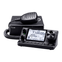
Table of Contents

Other manuals for Icom IC-7100

Questions and Answers:

Question and Answer IconNeed help?

Do you have a question about the Icom IC-7100 and is the answer not in the manual?

Icom IC-7100 Specifications

General IconGeneral
Supply13.8 V DC ±15%
Voltage13.8 V DC
Operating Temperature-10°C to +60°C
Frequency Coverage0.030-199.999 MHz, 400-470 MHz
ModesSSB, CW, AM, FM, DV
Output PowerHF/50MHz: 100W, 144MHz: 50W, 430MHz: 35W
Receiver TypeSuperheterodyne
Antenna ConnectorSO-239 (HF/50MHz/144MHz), N-type (430MHz)
WeightMain unit: 2.3 kg
TypeBase/Mobile
Frequency Range TX1.8–54 MHz, 144–148 MHz, 430–450 MHz
Frequency Range RX0.030–199.999 MHz, 400–470 MHz
Memories505
Current ConsumptionTX: 22 A, RX: 1.2 A

Related product manuals