3-6
3
OPTIONS
Specications
Frequency coverage: 1�9–54 MHz
Maximum input power: 120 W
Minimum tuning power: 8 W
Matching impedance range:
Tuning accuracy: Less than SWR 1�5:1
Insertion loss: Less than 1�0 dB
(after tuning)
Power supply requirements:
13�8 V DC/1 A
(supplied from the
transceiver’s ACC socket)
Dimensions (mm/in):
167 (W) × 58�6 (H) ×225 (D) mm
6
9
16 (W) × 2
5
17 (H) × 8
7
8 (D) in
Weight (approximate): 2�3 kg, 5 lb 1
1
8 oz
Supplied accessories
• coaxial cable (1 m),
• ACC cable (DIN 13 pins)
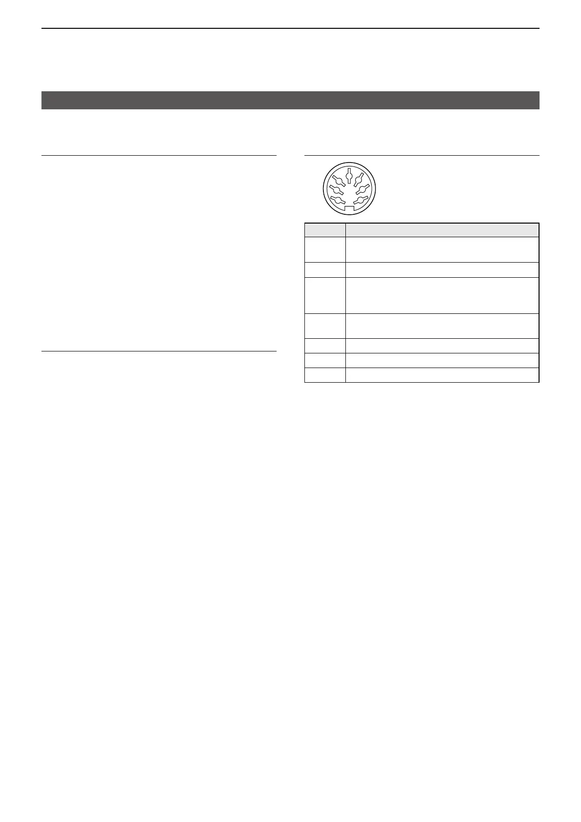
Connector information for the ACC 2 socket
1
2
3
4
76
5
Pin Description
1 8 V
Regulated 8 V output�
(10 mA maximum)
2 GND
Connects to ground�
3 SEND
Input/output pin
Goes to ground when transmitting (20 mA
maximum�) Transmits when grounded�
4 BAND
Band voltage output
(Depends on the selected band, 0 to 8�0 V�)
5 ALC
ALC output voltage (–4 to 0 V�)
6 NC
No connection�
7 13�8 V
13�8 V output when power is ON (1 A maximum�)
Connecting an external antenna tuner
D Using the AT-180

 Loading...


